SI Controller
Spark-ignition engine controller that uses the driver torque request
Libraries:
Powertrain Blockset /
Propulsion /
Combustion Engine Controllers
Description
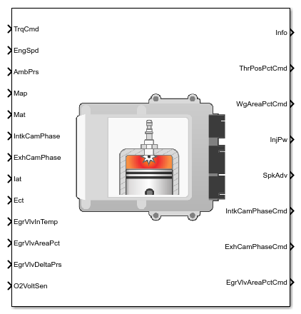
The SI Controller block implements a spark-ignition (SI) controller that uses the driver torque request to calculate the open-loop air, fuel, and spark actuator commands that are required to meet the driver demand.
You can use the SI Controller block in engine control design or performance, fuel economy, and emission tradeoff studies. The core engine, throttle, and turbocharger wastegate subsystems require the commands that are output from the SI Controller block.
The block uses the commanded torque and engine speed to determine these open-loop actuator commands:
Throttle position percent
Wastegate area percent
Injector pulse-width
Spark advance
Intake cam phaser angle
Exhaust cam phaser angle
Exhaust gas recirculation (EGR) valve area percent
The SI Controller block has two subsystems:
The
Controllersubsystem — Determines the commands based on the commanded torque, measured engine speed, and estimated cylinder air mass.The
Estimatorsubsystem — Determines the estimated air mass flow, torque, and exhaust gas temperature from intake manifold gas pressure, intake manifold gas temperature, engine speed, and cam phaser positions.
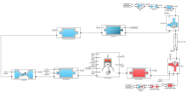
The figure illustrates the signal flow.
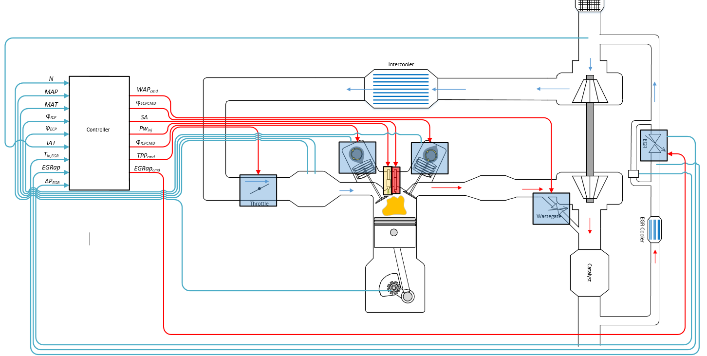
The figure uses these variables.
| N | Engine speed |
| MAP | Cycle average intake manifold pressure |
| IAT |
Intake air temperature |
| Tin,EGR |
Temperature at EGR valve inlet |
| MAT | Cycle average intake manifold gas absolute temperature |
| , |
Intake cam phaser angle and intake cam phaser angle command, respectively |
|
, |
Exhaust cam phaser angle and exhaust cam phaser angle command, respectively |
| EGRap, EGRapcmd |
EGR valve area percent and EGR valve area percent command, respectively |
| ΔPEGR |
Pressure difference at EGR valve inlet and outlet |
| WAPcmd |
Turbocharger wastegate area percent command |
| SA |
Spark advance |
|
Fuel injector pulse-width | |
| TPPcmd |
Throttle position percent command |
The Model-Based Calibration Toolbox™ was used to develop the tables that are available with the Powertrain Blockset™.
Controller
The block determines the commanded engine load (that is, normalized cylinder air mass) from a lookup table that is a function of commanded torque and measured engine speed.
To achieve the commanded load, the controller sets the throttle position percent and turbocharger wastegate area percent using feed forward lookup tables. The lookup tables are functions of the commanded load and measured engine speed.
To determine the cam phaser angle commands, the block uses lookup tables that are functions of estimated engine load and measured engine speed.
The block calculates the desired engine load using this equation.
The equations use these variables.
| Lest | Estimated engine load |
| Lcmd | Commanded engine load |
| N | Engine speed |
| Tcmd | Commanded engine torque |
| TAPcmd | Throttle area percent command |
| TPPcmd | Throttle position percent command |
| WAPcmd | Turbocharger wastegate area percent command |
Crankshaft revolutions per power stroke | |
Standard pressure | |
Standard temperature | |
Ideal gas constant for air and burned gas mixture | |
Displaced volume | |
Estimated engine air mass flow |
The controller subsystem uses these lookup tables for the air calculations.
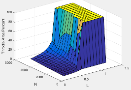
The throttle area percent command lookup table, , is a function of commanded load and engine speed
where:
TAPcmd is throttle area percentage command, in percent.
Lcmd=L is commanded engine load, dimensionless.
N is engine speed, in rpm.
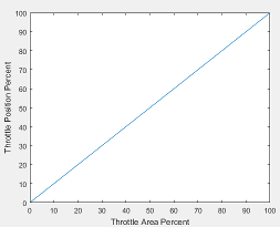
To account for the non-linearity of the throttle position to throttle area, the throttle position percent lookup table linearizes the open-loop air mass flow control.
The throttle position percent command lookup table, , is a function of the throttle area percentage command
where:
TPPcmd is throttle position percentage command, in percent.
TAPcmd is throttle area percentage command, in percent.
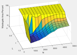
The wastegate area percent command lookup table, , is a function of the commanded engine load and engine speed
where:
WAPcmd is wastegate area percentage command, in percent.
Lcmd=L is commanded engine load, dimensionless.
N is engine speed, in rpm.
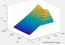
The commanded engine load lookup table, , is a function of the commanded torque and engine speed
where:
Lcmd=L is commanded engine load, dimensionless.
Tcmd is commanded torque, in N·m.
N is engine speed, in rpm.
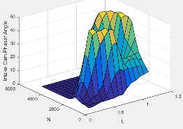
The intake cam phaser angle command lookup table, , is a function of the engine load and engine speed
where:
is commanded intake cam phaser angle, in crank degrees advance from park.
Lest=L is commanded engine load, dimensionless.
N is engine speed, in rpm.
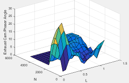
The exhaust cam phaser angle command lookup table, , is a function of the engine load and engine speed
where:
is commanded exhaust cam phaser angle, in crank degrees retard from park.
Lest=L is estimated engine load, dimensionless.
N is engine speed, in rpm.
EGR is typically expressed as a percent of total intake port flow.
To calculate the EGR area percent command, the block uses equations and a lookup table.
|
Equations |
|
|
Lookup table |
The EGR area percent command, EGRapcmd, lookup table is a function of the normalized mass flow and pressure ratio where:
|
The equations and table use these variables.
| EGRap, EGRapcmd |
EGR valve area percent and EGR valve area percent command, respectively |
| EGRpct,cmd |
EGR percent command |
|
Commanded standard mass flow | |
|
Maximum standard mass flow | |
|
Commanded mass flow | |
|
Estimated intake port mass flow | |
| Tstd, Pstd |
Standard temperature and pressure |
| Tin,EGR |
Temperature at EGR valve inlet |
| Pout,EGR, Pin,EGR |
Pressure at EGR valve inlet and outlet, respectively |
The air-fuel ratio (AFR) impacts three-way-catalyst (TWC) conversion efficiency, torque production, and combustion temperature. The engine controller manages AFR by commanding injector pulse-width from a desired relative AFR. The relative AFR, , is the ratio between the commanded AFR and the stoichiometric AFR of the fuel.
The SI Controller block accounts for the extra fuel delivered to the SI engine during startup. If the engine speed is greater than the startup engine cranking speed, the SI Controller block enriches the optimal AFR, lambda, with an exponentially decaying delta lambda. To initialize the delta lambda, the block uses the engine coolant temperature at startup. The delta lambda exponentially decays to zero based on a time constant that is a function of the engine coolant temperature.
You can configure the block for open-loop and closed-loop AFR control.
To | Use | Controls > Fuel > Closed-loop feedback Parameter Setting |
|---|---|---|
| (default) Open-loop control |
|
| Closed-loop control |
|
Open-Loop Control
To create an input port for the commanded AFR (lambda), on the Controls > Fuel > Open-loop fuel pane, select Input lambda.
You can manually tune the catalyst for maximum efficiency during open-loop AFR control with or without dither. If you want to implement dither during open-loop control, on the Fuel tab, on the Closed-loop fuel pane, select Dither.
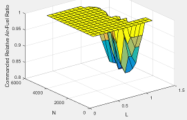
By default, the block is configured to use a lookup table for the commanded AFR.
The commanded lambda, , lookup table is a function of estimated engine load and measured engine speed
where:
is commanded relative AFR, dimensionless.
Lest=L is commanded engine load, dimensionless.
N is engine speed, in rpm.
The block calculates the estimated fuel mass flow rate using the commanded lambda, , stoichiometric AFR, and estimated air mass flow rate.
The block assumes that the battery voltage and fuel pressure are at nominal settings where pulse-width correction is not necessary. The commanded fuel injector pulse-width is proportional to the fuel mass per injection. The fuel mass per injection is calculated from the commanded fuel mass flow rate, engine speed, and the number of cylinders.
Closed-Loop Control
TWC converters are most efficient when the exhaust AFR is near the stoichiometric AFR, where the air and fuel burn most completely. Around this ideal point, the AFR is within the catalyst window in which the catalyst is most efficient at converting carbon monoxide, hydrocarbons, and nitrogen oxides to non-harmful exhaust products. Empirical studies show that oscillating the AFR around stoichiometry at an optimized AFR frequency, amplitude, and bias widens the TWC window, increasing catalyst conversion efficiency in the presence of unavoidable disturbances.
To keep production hardware costs down, AFR control systems include inexpensive switching oxygen sensors positioned in the engine exhaust stream upstream and downstream of the catalyst. The oxygen sensors have a narrow range. Essentially, they switch between too lean (i.e., more air is available than is required to burn the available fuel) and too rich (i.e., more air is available than is required to burn the available fuel).
The block implements a period-based method to control the average AFR at a value within the catalyst window for maximum conversion efficiency. Period-based AFR control is independent of the transport delay across the engine from the fuel injection point to the sensor measurement point. For more information about the method, see Developing a Period-Based Air-Fuel Ratio Controller Using a Low-Cost Switching Sensor.
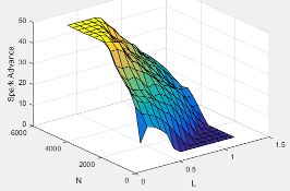
Spark advance is the crank angle before top dead center (BTDC) of the power stroke when the spark is delivered. The spark advance has an impact on engine efficiency, torque, exhaust temperature, knock, and emissions.
The spark advance lookup table is a function of estimated load and engine speed.
where:
SA is spark advance, in crank advance degrees.
Lest=L is commanded engine load, dimensionless.
N is engine speed, in rpm.
The equations use these variables.
| Lest | Estimated engine load, based on normalized cylinder air mass |
| N | Engine speed |
Lookup table for spark advance | |
| N | Spark advance |
When the commanded torque is below a threshold value, the idle speed controller regulates the engine speed.
| If | Idle Speed Controller |
|---|---|
| Trqcmd,input < Trqidlecmd,enable | Enabled |
| Trqidlecmd,enable ≤ Trqcmd,input | Not enabled |
The idle speed controller uses a discrete PI controller to regulate the target idle speed by commanding a torque.
The PI controller uses this transfer function:
The idle speed commanded torque must be less than the maximum commanded torque:
0 ≤ Trqidlecomd ≤Trqidlecmd,max
Idle speed control is active under these conditions. If the commanded input torque drops below the threshold for enabling the idle speed controller (Trqcmd,input < Trqidlecmd,enable), the commanded engine torque is given by:
Trqcmd = max(Trqcmd,input,Trqidlecmd).
The equations use these variables.
| Trqcmd | Commanded engine torque |
| Trqcmd,input | Input commanded engine torque |
| Trqidlecmd,enable | Threshold for enabling idle speed controller |
| Trqidlecmd | Idle speed controller commanded torque |
| Trqidlecmd,max | Maximum commanded torque |
| Nidle | Base idle speed |
| Kp,idle | Idle speed controller proportional gain |
| Ki,idle | Idle speed controller integral gain |
To prevent over revving the engine, the block implements an engine speed limit controller that limits the engine speed to the value specified by the Rev-limiter speed threshold parameter on the Controls > Idle Speed tab.
If the engine speed, N, exceeds the engine speed limit, Nlim, the block sets the commanded engine torque to 0.
To smoothly transition the torque command to 0 as the engine speed approaches the speed limit, the block implements a lookup table multiplier. The lookup table multiplies the torque command by a value that ranges from 0 (engine speed exceeds limit) to 1 (engine speed does not exceed the limit).
Estimator
The estimator subsystem determines the estimated air mass flow, torque, EGR mass flow, and exhaust temperature based on sensor feedback and calibration parameters.
|
Estimated engine air mass flow | |
| Trqest |
Estimated engine torque |
| Texh,est |
Estimated engine exhaust temperature |
|
Estimated low-pressure EGR mass flow |
To calculate engine air mass flow, configure the SI engine to use either of these air mass flow models.
| Air Mass Flow Model | Description |
|---|---|
| SI Engine Speed-Density Air Mass Flow Model |
Uses the speed-density equation to calculate the engine air mass flow, relating the engine air mass flow to the intake manifold pressure and engine speed. Consider using this air mass flow model in engines with fixed valvetrain designs. |
| SI Engine Dual-Independent Cam Phaser Air Mass Flow Model |
To calculate the engine air mass flow, the dual-independent cam phaser model uses:
In contrast to typical embedded air mass flow calculations based on direct air mass flow measurement with an air mass flow (MAF) sensor, this air mass flow model offers:
|
To determine the estimated air mass flow, the block uses the intake air mass fraction. The EGR mass fraction at the intake port lags the mass fraction near the EGR valve outlet. To model the lag, the block uses a first order system with a time constant.
The remainder of the gas is air.
The equations use these variables.
| yintk,EGR,est |
Estimated intake manifold EGR mass fraction |
| yintk,air,est |
Estimated intake manifold air mass fraction |
|
Estimated low-pressure EGR mass flow | |
|
Estimated intake port mass flow | |
|
τEGR | EGR time constant |
To calculate the brake torque, configure the SI engine to use either of these torque models.
| Brake Torque Model | Description |
|---|---|
| SI Engine Torque Structure Model | For the structured brake torque calculation, the SI engine uses tables for the inner torque, friction torque, optimal spark, spark efficiency, and lambda efficiency. If you select Crank angle pressure and torque on the block Torque tab, you can:
|
| SI Engine Simple Torque Model |
For the simple brake torque calculation, the SI engine block uses a torque lookup table map that is a function of engine speed and load. |
The controller estimates low-pressure mass flow, EGR valve inlet pressure, and EGR valve outlet pressure using an algorithm developed by F. Liu and J. Pfeiffer. The estimator requires measured EGR valve differential pressure, EGR valve area percent, intake air temperature, and EGR valve inlet temperature.
To estimate the EGR valve commands, the block uses:
Equations
Tables
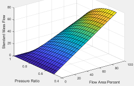
The EGR valve standard mass flow lookup table is a function of EGR valve area percent and the pressure ratio
where:
is EGR valve standard mass flow, dimensionless.
EGRap is EGR valve flow area percent, in percent.
is the pressure ratio, dimensionless.
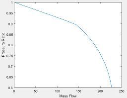
The pressure ratio is a function of the standard mass flow
where:
is standard mass flow, in g/s.
is pressure ratio, dimensionless.
The equations use these variables.
| EGRap |
EGR valve area percent command |
| IAT |
Intake air temperature |
| , |
Standard air and EGR valve mass flow, respectively |
| , |
Estimated air and EGR valve mass flow, respectively |
| Tstd, Pstd |
Standard temperature and pressure |
| Tamb, Pamb |
Ambient temperature and pressure |
| ΔPEGR |
Pressure difference at EGR valve inlet and outlet |
| Tin,EGR, Tout,EGR |
Temperature at EGR valve inlet and outlet, respectively |
| Pin,EGR, Pout,EGR |
Pressure at EGR valve inlet and outlet, respectively |
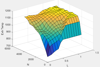
The exhaust temperature lookup table, , is a function of engine load and engine speed
where:
Texh is engine exhaust temperature, in K.
L is normalized cylinder air mass or engine load, dimensionless.
N is engine speed, in rpm.
Examples

Build Conventional Vehicle Model
Build a vehicle with an internal combustion engine using the conventional vehicle reference application.
Calibrate, Validate, and Optimize SI Engine with Dynamometer Test Harness
Simulate a spark-ignition (SI) engine and controller under a dynamometer test harness using the SI engine dynamometer reference application.
Ports
Input
Output
Parameters
Configuration
To calculate engine air mass flow, configure the SI engine to use either of these air mass flow models.
| Air Mass Flow Model | Description |
|---|---|
| SI Engine Speed-Density Air Mass Flow Model |
Uses the speed-density equation to calculate the engine air mass flow, relating the engine air mass flow to the intake manifold pressure and engine speed. Consider using this air mass flow model in engines with fixed valvetrain designs. |
| SI Engine Dual-Independent Cam Phaser Air Mass Flow Model |
To calculate the engine air mass flow, the dual-independent cam phaser model uses:
In contrast to typical embedded air mass flow calculations based on direct air mass flow measurement with an air mass flow (MAF) sensor, this air mass flow model offers:
|
Programmatic Use
To set the block parameter value programmatically, use
the set_param function.
To get the block parameter value
programmatically, use the get_param function.
| Parameter: | AirEstOptionPopup |
| Values: | Dual Variable Cam
Phasing (default) | Simple Speed-Density |
| Data Types: | character vector |
Dependencies
The table summarizes the parameter dependencies.
| Air Mass Flow Estimation Model | Enables Parameters on Estimation > Air Tab |
|---|---|
| Cylinder volume at intake valve close table, f_vivc Cylinder volume intake cam phase breakpoints, f_vivc_icp_bpt Cylinder trapped mass correction factor, f_tm_corr Normalized density breakpoints, f_tm_corr_nd_bpt Engine speed breakpoints, f_tm_corr_n_bpt Air mass flow, f_mdot_air Exhaust cam phase breakpoints, f_mdot_air_ecp_bpt Trapped mass flow breakpoints, f_mdot_trpd_bpt Air mass flow correction factor, f_mdot_air_corr Engine load breakpoints for air mass flow correction, f_mdot_air_corr_ld_bpt Engine speed breakpoints for air mass flow correction, f_mdot_air_n_bpt |
| Speed-density volumetric efficiency, f_nv Speed-density intake manifold pressure breakpoints, f_nv_prs_bpt Speed-density engine speed breakpoints, f_nv_n_bpt |
To calculate the brake torque, configure the SI engine to use either of these torque models.
| Brake Torque Model | Description |
|---|---|
| SI Engine Torque Structure Model | For the structured brake torque calculation, the SI engine uses tables for the inner torque, friction torque, optimal spark, spark efficiency, and lambda efficiency. If you select Crank angle pressure and torque on the block Torque tab, you can:
|
| SI Engine Simple Torque Model |
For the simple brake torque calculation, the SI engine block uses a torque lookup table map that is a function of engine speed and load. |
Programmatic Use
To set the block parameter value programmatically, use
the set_param function.
To get the block parameter value
programmatically, use the get_param function.
| Parameter: | TrqEstOptionPopup |
| Values: | Torque
Structure (default) | Simple Torque Lookup |
| Data Types: | character vector |
Dependencies
The table summarizes the parameter dependencies.
| Torque Estimation Model | Enables Parameters on Estimation > Torque Tab |
|---|---|
| Inner torque table, f_tq_inr Friction torque table, f_tq_fric Engine temperature modifier on friction torque, f_fric_temp_mod Engine temperature modifier breakpoints, f_fric_temp_bpt Pumping torque table, f_tq_pump Optimal spark table, f_sa_opt Inner torque load breakpoints, f_tq_inr_l_bpt Inner torque speed breakpoints, f_tq_inr_n_bpt Spark efficiency table, f_m_sa Spark retard from optimal, f_del_sa_bpt Lambda efficiency, f_m_lam Lambda breakpoints, f_m_lam_bpt |
| Torque table, f_tq_nl Torque table load breakpoints, f_tq_nl_l_bpt Torque table speed breakpoints, f_tq_nl_n_bpt |
Controls
Air
The commanded engine load lookup table, , is a function of the commanded torque and engine speed
where:
Lcmd=L is commanded engine load, dimensionless.
Tcmd is commanded torque, in N·m.
N is engine speed, in rpm.
Programmatic Use
To set the block parameter value programmatically, use
the set_param function.
To get the block parameter value
programmatically, use the get_param function.
| Parameter: | f_lcmd |
| Values: | array |
| Data Types: | double |
The throttle area percent command lookup table, , is a function of commanded load and engine speed
where:
TAPcmd is throttle area percentage command, in percent.
Lcmd=L is commanded engine load, dimensionless.
N is engine speed, in rpm.
Programmatic Use
To set the block parameter value programmatically, use
the set_param function.
To get the block parameter value
programmatically, use the get_param function.
| Parameter: | f_tap |
| Values: | array |
| Data Types: | double |
The throttle position percent command lookup table, , is a function of the throttle area percentage command
where:
TPPcmd is throttle position percentage command, in percent.
TAPcmd is throttle area percentage command, in percent.
Programmatic Use
To set the block parameter value programmatically, use
the set_param function.
To get the block parameter value
programmatically, use the get_param function.
| Parameter: | f_tpp |
| Values: | [0 100] (default) | vector |
| Data Types: | double |
Throttle area percent to position percent area breakpoints, dimensionless.
Programmatic Use
To set the block parameter value programmatically, use
the set_param function.
To get the block parameter value
programmatically, use the get_param function.
| Parameter: | f_tpp_tap_bpt |
| Values: | [0 100] (default) | vector |
| Data Types: | double |
The wastegate area percent command lookup table, , is a function of the commanded engine load and engine speed
where:
WAPcmd is wastegate area percentage command, in percent.
Lcmd=L is commanded engine load, dimensionless.
N is engine speed, in rpm.
Programmatic Use
To set the block parameter value programmatically, use
the set_param function.
To get the block parameter value
programmatically, use the get_param function.
| Parameter: | f_wap |
| Values: | array |
| Data Types: | double |
The intake cam phaser angle command lookup table, , is a function of the engine load and engine speed
where:
is commanded intake cam phaser angle, in crank degrees advance from park.
Lest=L is commanded engine load, dimensionless.
N is engine speed, in rpm.
Programmatic Use
To set the block parameter value programmatically, use
the set_param function.
To get the block parameter value
programmatically, use the get_param function.
| Parameter: | f_icp |
| Values: | array |
| Data Types: | double |
The exhaust cam phaser angle command lookup table, , is a function of the engine load and engine speed
where:
is commanded exhaust cam phaser angle, in crank degrees retard from park.
Lest=L is estimated engine load, dimensionless.
N is engine speed, in rpm.
Programmatic Use
To set the block parameter value programmatically, use
the set_param function.
To get the block parameter value
programmatically, use the get_param function.
| Parameter: | f_ecp |
| Values: | array |
| Data Types: | double |
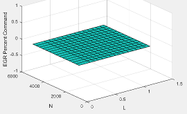
The EGR percent command, EGRpct,cmd, lookup table is a function of estimated engine load and engine speed
where:
EGRpct,cmd is commanded EGR percent, dimensionless.
Lest=L is estimated engine load, dimensionless.
N is engine speed, in rpm.
Programmatic Use
To set the block parameter value programmatically, use
the set_param function.
To get the block parameter value
programmatically, use the get_param function.
| Parameter: | f_egrpct_cmd |
| Values: | array |
| Data Types: | double |
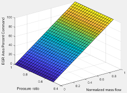
The EGR area percent command, EGRapcmd, lookup table is a function of the normalized mass flow and pressure ratio
where:
EGRapcmd is commanded EGR area percent, dimensionless.
is the normalized mass flow, dimensionless.
is the pressure ratio, dimensionless.
Programmatic Use
To set the block parameter value programmatically, use
the set_param function.
To get the block parameter value
programmatically, use the get_param function.
| Parameter: | f_egr_areapct_cmd |
| Values: | array |
| Data Types: | double |
Fuel
The commanded lambda, , lookup table is a function of estimated engine load and measured engine speed
where:
is commanded relative AFR, dimensionless.
Lest=L is commanded engine load, dimensionless.
N is engine speed, in rpm.
Programmatic Use
To set the block parameter value programmatically, use
the set_param function.
To get the block parameter value
programmatically, use the get_param function.
| Parameter: | f_lamcmd |
| Values: | array |
| Data Types: | double |
Dependencies
To create this parameter, on the Fuel tab, on the Open-loop fuel pane, clear Input lambda.
Load breakpoints, dimensionless.
Programmatic Use
To set the block parameter value programmatically, use
the set_param function.
To get the block parameter value
programmatically, use the get_param function.
| Parameter: | f_lamcmd_ld_bpt |
| Values: | vector |
| Data Types: | double |
Dependencies
To create this parameter, on the Fuel tab, on the Open-loop fuel pane, clear Input lambda.
Speed breakpoints, in rpm.
Programmatic Use
To set the block parameter value programmatically, use
the set_param function.
To get the block parameter value
programmatically, use the get_param function.
| Parameter: | f_lamcmd_n_bpt |
| Values: | vector |
| Data Types: | double |
Dependencies
To create this parameter, on the Fuel tab, on the Open-loop fuel pane, clear Input lambda.
Engine startup lambda enrichment delta as a function of coolant temperature, dimensionless.
The SI Controller block uses this parameter to account for the extra fuel delivered to the spark-ignition (SI) engine during startup. If the engine speed is greater than the Engine cranking speed parameter, the SI Controller block enriches the optimal relative air-fuel ratio (lambda) with an exponentially decaying delta lambda. To initialize the delta lambda, the block uses the Engine startup lambda enrichment delta vs coolant temperature parameter to create a lambda enrichment table that is a function of the engine coolant temperature. The delta lambda exponentially decays to zero based on a time constant specified with the Engine startup lambda enrichment delta time constant vs coolant temperature parameter.
Programmatic Use
To set the block parameter value programmatically, use
the set_param function.
To get the block parameter value
programmatically, use the get_param function.
| Parameter: | f_startup_lambda_delta |
| Values: | [0.5 0.3 0.2 0] (default) | vector |
| Data Types: | double |
Dependencies
To create this parameter, on the Fuel tab, on the Open-loop fuel pane, clear Input lambda.
Engine startup lambda enrichment delta time constant versus coolant temperature, in s.
The SI Controller block uses this parameter to account for the extra fuel delivered to the spark-ignition (SI) engine during startup. If the engine speed is greater than the Engine cranking speed parameter, the SI Controller block enriches the optimal relative air-fuel ratio (lambda) with an exponentially decaying delta lambda. To initialize the delta lambda, the block uses the Engine startup lambda enrichment delta vs coolant temperature parameter to create a lambda enrichment table that is a function of the engine coolant temperature. The delta lambda exponentially decays to zero based on a time constant specified with the Engine startup lambda enrichment delta time constant vs coolant temperature parameter.
Programmatic Use
To set the block parameter value programmatically, use
the set_param function.
To get the block parameter value
programmatically, use the get_param function.
| Parameter: | f_startup_lambda_delta_timecnst |
| Values: | [90 40 12 0] (default) | vector |
| Data Types: | double |
Dependencies
To create this parameter, on the Fuel tab, on the Open-loop fuel pane, clear Input lambda.
Engine startup coolant temperature breakpoints, in C.
The SI Controller block uses this parameter to account for the extra fuel delivered to the spark-ignition (SI) engine during startup. If the engine speed is greater than the Engine cranking speed parameter, the SI Controller block enriches the optimal relative air-fuel ratio (lambda) with an exponentially decaying delta lambda. To initialize the delta lambda, the block uses the Engine startup lambda enrichment delta vs coolant temperature parameter to create a lambda enrichment table that is a function of the engine coolant temperature. The delta lambda exponentially decays to zero based on a time constant specified with the Engine startup lambda enrichment delta time constant vs coolant temperature parameter.
Programmatic Use
To set the block parameter value programmatically, use
the set_param function.
To get the block parameter value
programmatically, use the get_param function.
| Parameter: | f_startup_ect_bpt |
| Values: | [-40 0 20 50] (default) | vector |
| Data Types: | double |
Dependencies
To create this parameter, on the Fuel tab, on the Open-loop fuel pane, clear Input lambda.
Select option to minimize the commanded air-fuel-ratio (lambda), λcmd error.
Programmatic Use
To set the block parameter value programmatically, use
the set_param function.
To get the block parameter value
programmatically, use the get_param function.
| Parameter: | ClsdLpFuelEn |
| Values: | off (default) | on |
| Data Types: | character array |
Configure the block to model dither. For open-loop analysis, select this option to tune for maximum catalytic conversion efficiency.
Programmatic Use
To set the block parameter value programmatically, use
the set_param function.
To get the block parameter value
programmatically, use the get_param function.
| Parameter: | OpenLpDitherEn |
| Values: | off (default) | on |
| Data Types: | character array |
Dependencies
By default, selecting Closed-loop feedback configures the block to model dither.
To enable this parameter for open-loop air-fuel-ratio (lambda) commands, clear Closed-loop feedback.
Selecting this parameter enables these parameters:
Lambda dither amplitude, LambdaDitherAmp
Lambda dither frequency, LambdaDitherFrq
Closed-loop fuel proportional gain, dimensionless.
Programmatic Use
To set the block parameter value programmatically, use
the set_param function.
To get the block parameter value
programmatically, use the get_param function.
| Parameter: | ClsdLpFuelPGain |
| Values: | 0.005 (default) | scalar |
| Data Types: | double |
Dependencies
To enable this parameter, on the Fuel tab, on the Closed-loop fuel pane, select Closed-loop feedback.
Closed-loop fuel integral gain, dimensionless.
Programmatic Use
To set the block parameter value programmatically, use
the set_param function.
To get the block parameter value
programmatically, use the get_param function.
| Parameter: | ClsdLpFuelIGain |
| Values: | 0.05 (default) | scalar |
| Data Types: | double |
Dependencies
To enable this parameter, on the Fuel tab, on the Closed-loop fuel pane, select Closed-loop feedback.
Closed-loop fuel integrator limit, dimensionless.
Programmatic Use
To set the block parameter value programmatically, use
the set_param function.
To get the block parameter value
programmatically, use the get_param function.
| Parameter: | ClsdLpFuelIntgLmt |
| Values: | 0.2 (default) | scalar |
| Data Types: | double |
Dependencies
To enable this parameter, on the Fuel tab, on the Closed-loop fuel pane, select Closed-loop feedback.
Lambda dither amplitude, dimensionless.
Programmatic Use
To set the block parameter value programmatically, use
the set_param function.
To get the block parameter value
programmatically, use the get_param function.
| Parameter: | LambdaDitherAmp |
| Values: | 0.03 (default) | scalar |
| Data Types: | double |
Dependencies
To enable this parameter, on the Fuel tab, on the Closed-loop fuel pane, select either Closed-loop feedback or Dither.
Lambda dither frequency, in Hz.
Programmatic Use
To set the block parameter value programmatically, use
the set_param function.
To get the block parameter value
programmatically, use the get_param function.
| Parameter: | LambdaDitherFrq |
| Values: | 0.75 (default) | scalar |
| Data Types: | double |
Dependencies
To enable this parameter, on the Fuel tab, on the Closed-loop fuel pane, select either Closed-loop feedback or Dither.
Oxygen sensor stoichiometric reset voltage, O2ResetStoichVoltSen, in mV.
Programmatic Use
To set the block parameter value programmatically, use
the set_param function.
To get the block parameter value
programmatically, use the get_param function.
| Parameter: | O2ResetStoichVoltSen |
| Values: | 2500 (default) | scalar |
| Data Types: | double |
Dependencies
To enable this parameter, on the Fuel tab, on the Closed-loop fuel pane, select Closed-loop feedback.
Oxygen sensor minimum voltage reset, O2ResetMinVoltSen, in mV.
Programmatic Use
To set the block parameter value programmatically, use
the set_param function.
To get the block parameter value
programmatically, use the get_param function.
| Parameter: | O2ResetMinVoltSen |
| Values: | 0 (default) | scalar |
| Data Types: | double |
Dependencies
To enable this parameter, on the Fuel tab, on the Closed-loop fuel pane, select Closed-loop feedback.
Oxygen sensor maximum voltage reset, O2ResetMaxVoltSen, in mV.
Programmatic Use
To set the block parameter value programmatically, use
the set_param function.
To get the block parameter value
programmatically, use the get_param function.
| Parameter: | O2ResetMaxVoltSen |
| Values: | 5000 (default) | scalar |
| Data Types: | double |
Dependencies
To enable this parameter, on the Fuel tab, on the Closed-loop fuel pane, select Closed-loop feedback.
Oxygen sensor voltage learn update period, O2LearnUpdatePerSen, in mV.
Programmatic Use
To set the block parameter value programmatically, use
the set_param function.
To get the block parameter value
programmatically, use the get_param function.
| Parameter: | O2LearnUpdatePerSen |
| Values: | 4 (default) | scalar |
| Data Types: | double |
Dependencies
To enable this parameter, on the Fuel tab, on the Closed-loop fuel pane, select Closed-loop feedback.
Oxygen sensor voltage amplitude minimum, O2AmpMinVoltSen, in mV.
Programmatic Use
To set the block parameter value programmatically, use
the set_param function.
To get the block parameter value
programmatically, use the get_param function.
| Parameter: | O2AmpMinVoltSen |
| Values: | 250 (default) | scalar |
| Data Types: | double |
Dependencies
To enable this parameter, on the Fuel tab, on the Closed-loop fuel pane, select Closed-loop feedback.
Oxygen sensor ready voltage, O2ReadyVoltSen, in mV.
Programmatic Use
To set the block parameter value programmatically, use
the set_param function.
To get the block parameter value
programmatically, use the get_param function.
| Parameter: | O2ReadyVoltSen |
| Values: | 1150 (default) | scalar |
| Data Types: | double |
Dependencies
To enable this parameter, on the Fuel tab, on the Closed-loop fuel pane, select Closed-loop feedback.
Oxygen sensor not ready voltage, O2NotReadyVoltSen, in mV.
Programmatic Use
To set the block parameter value programmatically, use
the set_param function.
To get the block parameter value
programmatically, use the get_param function.
| Parameter: | O2NotReadyVoltSen |
| Values: | 1950 (default) | scalar |
| Data Types: | double |
Dependencies
To enable this parameter, on the Fuel tab, on the Closed-loop fuel pane, select Closed-loop feedback.
Spark
The spark advance lookup table is a function of estimated load and engine speed.
where:
SA is spark advance, in crank advance degrees.
Lest=L is commanded engine load, dimensionless.
N is engine speed, in rpm.
Programmatic Use
To set the block parameter value programmatically, use
the set_param function.
To get the block parameter value
programmatically, use the get_param function.
| Parameter: | f_sa |
| Values: | array |
| Data Types: | double |
Idle Speed
Torque to enable the idle speed controller, Trqidlecmd,enable, in N·m.
Programmatic Use
To set the block parameter value programmatically, use
the set_param function.
To get the block parameter value
programmatically, use the get_param function.
| Parameter: | Trq_idlecmd_enable |
| Values: | 1 (default) | scalar |
| Data Types: | double |
Maximum idle controller commanded torque, Trqidlecmd,max, in N·m.
Programmatic Use
To set the block parameter value programmatically, use
the set_param function.
To get the block parameter value
programmatically, use the get_param function.
| Parameter: | Trq_idlecmd_max |
| Values: | 50 (default) | scalar |
| Data Types: | double |
Proportional gain for idle speed control, Kp,idle, in N·m/rpm.
Programmatic Use
To set the block parameter value programmatically, use
the set_param function.
To get the block parameter value
programmatically, use the get_param function.
| Parameter: | Kp_idle |
| Values: | 0.05 (default) | scalar |
| Data Types: | double |
Integral gain for idle speed control, Ki,idle, in N·m/(rpm·s).
Programmatic Use
To set the block parameter value programmatically, use
the set_param function.
To get the block parameter value
programmatically, use the get_param function.
| Parameter: | Ki_idle |
| Values: | 0.2 (default) | scalar |
| Data Types: | double |
Engine speed limit, Nlim, in rpm.
If the engine speed, N, exceeds the engine speed limit, Nlim, the block sets the commanded engine torque to 0.
To smoothly transition the torque command to 0 as the engine speed approaches the speed limit, the block implements a lookup table multiplier. The lookup table multiplies the torque command by a value that ranges from 0 (engine speed exceeds limit) to 1 (engine speed does not exceed the limit).
Programmatic Use
To set the block parameter value programmatically, use
the set_param function.
To get the block parameter value
programmatically, use the get_param function.
| Parameter: | EngRevLim |
| Values: | 6000 (default) | scalar |
| Data Types: | double |
Stop-Start
Select to enable the engine stop-start logic. Selecting this option will activate additional parameters to modify the behavior of the Engine Stop-Start block.
Programmatic Use
To set the block parameter value programmatically, use
the set_param function.
To get the block parameter value
programmatically, use the get_param function.
| Parameter: | ESSEnable |
| Values: | off (default) | on |
| Data Types: | character vector |
Select to add a port to the engine controller block which enables or disables the stop-start logic.
Programmatic Use
To set the block parameter value programmatically, use
the set_param function.
To get the block parameter value
programmatically, use the get_param function.
| Parameter: | ESSExternalPortEnable |
| Values: | off (default) | on |
| Data Types: | character vector |
Dependencies
To enable this parameter, on the Stop-Start tab, select Enable Engine Stop-Start.
Engine stop time for the stop-start logic, in s.
Programmatic Use
To set the block parameter value programmatically, use
the set_param function.
To get the block parameter value
programmatically, use the get_param function.
| Parameter: | EngStopTime |
| Values: | 5 (default) | scalar |
| Data Types: | double |
Dependencies
To enable this parameter, on the Stop-Start tab, select Enable Engine Stop-Start.
Catalyst light off time for the stop-start logic, in s.
Programmatic Use
To set the block parameter value programmatically, use
the set_param function.
To get the block parameter value
programmatically, use the get_param function.
| Parameter: | CatLightOffTime |
| Values: | 0 (default) | scalar |
| Data Types: | double |
Dependencies
To enable this parameter, on the Stop-Start tab, select Enable Engine Stop-Start.
Sample time for the stop-start logic, in s.
Programmatic Use
To set the block parameter value programmatically, use
the set_param function.
To get the block parameter value
programmatically, use the get_param function.
| Parameter: | Ts |
| Values: | 0.01 (default) | scalar |
| Data Types: | double |
Dependencies
To enable this parameter, on the Stop-Start tab, select Enable Engine Stop-Start.
Estimation
Air
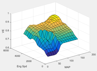
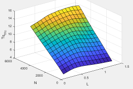
The engine volumetric efficiency lookup table, , is a function of intake manifold absolute pressure and engine speed
where:
is engine volumetric efficiency, dimensionless.
MAP is intake manifold absolute pressure, in KPa.
N is engine speed, in rpm.
Programmatic Use
To set the block parameter value programmatically, use
the set_param function.
To get the block parameter value
programmatically, use the get_param function.
| Parameter: | f_nv |
| Values: | array |
| Data Types: | double |
Dependencies
To enable this parameter, for the Air mass flow
estimation model parameter, select
Simple Speed-Density.
Intake manifold pressure breakpoints for speed-density volumetric efficiency lookup table, in KPa.
Programmatic Use
To set the block parameter value programmatically, use
the set_param function.
To get the block parameter value
programmatically, use the get_param function.
| Parameter: | f_nv_prs_bpt |
| Values: | vector |
| Data Types: | double |
Dependencies
To enable this parameter, for the Air mass flow
estimation model parameter, select
Simple Speed-Density.
Engine speed breakpoints for speed-density volumetric efficiency lookup table, in rpm.
Programmatic Use
To set the block parameter value programmatically, use
the set_param function.
To get the block parameter value
programmatically, use the get_param function.
| Parameter: | f_nv_n_bpt |
| Values: | vector |
| Data Types: | double |
Dependencies
To enable this parameter, for the Air mass flow
estimation model parameter, select
Simple Speed-Density.
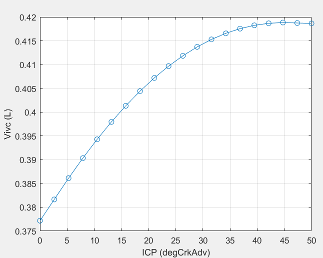
The cylinder volume at intake valve close table (IVC), is a function of the intake cam phaser angle
where:
is cylinder volume at IVC, in L.
is intake cam phaser angle in crank degrees of advance relative to the intake phaser park position.
Programmatic Use
To set the block parameter value programmatically, use
the set_param function.
To get the block parameter value
programmatically, use the get_param function.
| Parameter: | f_vivc |
| Values: | array |
| Data Types: | double |
Dependencies
To enable this parameter, for the Air mass flow
estimation model parameter, select Dual
Variable Cam Phasing.
Engine speed breakpoints, in rpm.
Programmatic Use
To set the block parameter value programmatically, use
the set_param function.
To get the block parameter value
programmatically, use the get_param function.
| Parameter: | f_tm_corr_n_bpt |
| Values: | vector |
| Data Types: | double |
Dependencies
To enable this parameter, for the Air mass flow
estimation model parameter, select Dual
Variable Cam Phasing.
Cylinder volume at intake valve close table breakpoints.
Programmatic Use
To set the block parameter value programmatically, use
the set_param function.
To get the block parameter value
programmatically, use the get_param function.
| Parameter: | f_vivc_icp_bpt |
| Values: | vector |
| Data Types: | double |
Dependencies
To enable this parameter, for the Air mass flow
estimation model parameter, select Dual
Variable Cam Phasing.
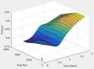
The trapped mass correction factor table, , is a function of the normalized density and engine speed
where:
, is trapped mass correction multiplier, dimensionless.
is normalized density, dimensionless.
N is engine speed, in rpm.
Programmatic Use
To set the block parameter value programmatically, use
the set_param function.
To get the block parameter value
programmatically, use the get_param function.
| Parameter: | f_tm_corr |
| Values: | array |
| Data Types: | double |
Dependencies
To enable this parameter, for the Air mass flow
estimation model parameter, select Dual
Variable Cam Phasing.
Normalized density breakpoints.
Programmatic Use
To set the block parameter value programmatically, use
the set_param function.
To get the block parameter value
programmatically, use the get_param function.
| Parameter: | f_tm_corr_nd_bpt |
| Values: | vector |
| Data Types: | double |
Dependencies
To enable this parameter, for the Air mass flow
estimation model parameter, select Dual
Variable Cam Phasing.
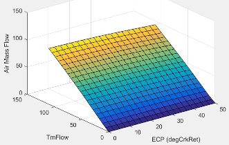
The phaser intake mass flow model lookup table is a function of exhaust cam phaser angles and trapped air mass flow
where:
is engine intake port mass flow at arbitrary cam phaser angles, in g/s.
is exhaust cam phaser angle in crank degrees of retard relative to the exhaust phaser park position.
is flow rate equivalent to corrected trapped mass at the current engine speed, in g/s.
Programmatic Use
To set the block parameter value programmatically, use
the set_param function.
To get the block parameter value
programmatically, use the get_param function.
| Parameter: | f_mdot_intk |
| Values: | array |
| Data Types: | double |
Dependencies
To enable this parameter, for the Air mass flow
estimation model parameter, select Dual
Variable Cam Phasing.
Exhaust cam phaser breakpoints for air mass flow lookup table.
Programmatic Use
To set the block parameter value programmatically, use
the set_param function.
To get the block parameter value
programmatically, use the get_param function.
| Parameter: | f_mdot_air_ecp_bpt |
| Values: | vector |
| Data Types: | double |
Dependencies
To enable this parameter, for the Air mass flow
estimation model parameter, select Dual
Variable Cam Phasing.
Trapped mass flow breakpoints for air mass flow lookup table.
Programmatic Use
To set the block parameter value programmatically, use
the set_param function.
To get the block parameter value
programmatically, use the get_param function.
| Parameter: | f_mdot_trpd_bpt |
| Values: | vector |
| Data Types: | double |
Dependencies
To enable this parameter, for the Air mass flow
estimation model parameter, select Dual
Variable Cam Phasing.
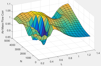
The intake air mass flow correction lookup table, , is a function of ideal load and engine speed
where:
is engine load (normalized cylinder air mass) at arbitrary cam phaser angles, uncorrected for final steady-state cam phaser angles, dimensionless.
N is engine speed, in rpm.
is engine intake air mass flow final correction at steady-state cam phaser angles, in g/s.
is engine intake port mass flow at arbitrary cam phaser angles, in g/s.
Programmatic Use
To set the block parameter value programmatically, use
the set_param function.
To get the block parameter value
programmatically, use the get_param function.
| Parameter: | f_mdot_air_corr |
| Values: | array |
| Data Types: | double |
Dependencies
To enable this parameter, for the Air mass flow
estimation model parameter, select Dual
Variable Cam Phasing.
Engine load breakpoints for air mass flow final correction.
Programmatic Use
To set the block parameter value programmatically, use
the set_param function.
To get the block parameter value
programmatically, use the get_param function.
| Parameter: | f_mdot_air_corr_ld_bpt |
| Values: | vector |
| Data Types: | double |
Dependencies
To enable this parameter, for the Air mass flow
estimation model parameter, select Dual
Variable Cam Phasing.
Engine speed breakpoints for air mass flow final correction.
Programmatic Use
To set the block parameter value programmatically, use
the set_param function.
To get the block parameter value
programmatically, use the get_param function.
| Parameter: | f_mdot_air_n_bpt |
| Values: | vector |
| Data Types: | double |
Dependencies
To enable this parameter, for the Air mass flow
estimation model parameter, select Dual
Variable Cam Phasing.
The pressure ratio is a function of the standard mass flow
where:
is standard mass flow, in g/s.
is pressure ratio, dimensionless.
Programmatic Use
To set the block parameter value programmatically, use
the set_param function.
To get the block parameter value
programmatically, use the get_param function.
| Parameter: | f_intksys_stdflow_pr |
| Values: | array |
| Data Types: | double |
The EGR valve standard mass flow lookup table is a function of EGR valve area percent and the pressure ratio
where:
is EGR valve standard mass flow, dimensionless.
EGRap is EGR valve flow area percent, in percent.
is the pressure ratio, dimensionless.
Programmatic Use
To set the block parameter value programmatically, use
the set_param function.
To get the block parameter value
programmatically, use the get_param function.
| Parameter: | f_egr_stdflow |
| Values: | array |
| Data Types: | double |
Torque
For the simple torque lookup table model, the SI engine uses a lookup table map that is a function of engine speed and load, , where:
is engine brake torque after accounting for spark advance, AFR, and friction effects, in N·m.
L is engine load, as a normalized cylinder air mass, dimensionless.
N is engine speed, in rpm.
The simple torque lookup model assumes that the calibration has negative torque values to indicate the non-firing engine load (L) versus speed (N) condition. The calibrated table (L-by-N) contains the non-firing data in the first table row (1-by-N). When the fuel delivered to the engine is zero, the model uses the data in the first table row (1-by-N) at or above 100 AFR. 100 AFR results from fuel cutoff or very lean operation where combustion cannot occur.
Dependencies
To enable this parameter, for the Torque model parameter,
select Simple Torque Lookup.
Engine load breakpoints, L, dimensionless.
Dependencies
To enable this parameter, for the Torque model parameter,
select Simple Torque Lookup.
Engine speed breakpoints, N, in rpm.
Dependencies
To enable this parameter, for the Torque model parameter,
select Simple Torque Lookup.
If you select Crank angle pressure and torque on the block Torque tab, you can:
Simulate advanced closed-loop engine controls in desktop simulations and on HIL bench, based on cylinder pressure recorded from a model or laboratory test as a function of crank angle.
Simulate driveline vibrations downstream of the engine due to high-frequency crankshaft torsionals.
Simulate engine misfires due to lean operation or spark plug fouling by using the injector pulse width input.
Simulate cylinder deactivation effect (closed intake and exhaust valves, no injected fuel) on individual cylinder pressures, mean-value airflow, mean-value torque, and crank-angle-based torque.
Simulate the fuel-cut effect on individual cylinder pressure, mean-value torque, and crank-angle-based torque.
Dependencies
To enable this parameter, set Torque model to
Torque Structure.
Cylinder pressure table Prs, as a function of speed N, load L, and crank angle M, in Pa.
Dependencies
To enable this parameter, for the Torque model parameter,
select Torque Structure. Select Crank angle
pressure and torque.
Brake torque table Tbrake, as a function of speed N, load L, and crank angle M, in N·m.
Dependencies
To enable this parameter, for the Torque model parameter,
select Torque Structure. Select Crank angle
pressure and torque.
Speed breakpoints, N, in rpm.
Dependencies
To enable this parameter, for the Torque model parameter,
select Torque Structure. Select Crank angle
pressure and torque.
Load breakpoints, L. No dimension.
Dependencies
To enable this parameter, for the Torque model parameter,
select Torque Structure. Select Crank angle
pressure and torque.
Crank angle breakpoints, M, in deg.
Dependencies
To enable this parameter, for the Torque model parameter,
select Torque Structure. Select Crank angle
pressure and torque.
Top dead center (TDC) compression angles by cylinder, in deg.
Dependencies
To enable this parameter, for the Torque model parameter,
select Torque Structure. Select Crank angle
pressure and torque.
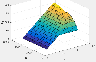
The inner torque lookup table, , is a function of engine speed and engine load, , where:
is inner torque based on gross indicated mean effective pressure, in N·m.
L is engine load at arbitrary cam phaser angles, corrected for final steady-state cam phaser angles, dimensionless.
N is engine speed, in rpm.
Dependencies
To enable this parameter, for the Torque model parameter,
select Torque Structure.
The friction torque lookup table, , is a function of engine speed and engine load, , where:
is friction torque offset to inner torque, in N·m.
L is engine load at arbitrary cam phaser angles, corrected for final steady-state cam phaser angles, dimensionless.
N is engine speed, in rpm.
Dependencies
To enable this parameter, for the Torque model parameter,
select Torque Structure.
Engine temperature modifier on friction torque, ƒfric,temp, dimensionless.
Dependencies
To enable this parameter, for the Torque model parameter,
select Torque Structure.
Engine temperature modifier breakpoints, in K.
Dependencies
To enable this parameter, for the Torque model parameter,
select Torque Structure.
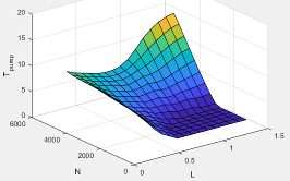
The pumping torque lookup
table, ƒTpump, is a function of engine load and engine
speed,
Tpump=ƒTpump(L,N), where:
Tpump is pumping torque, in N·m.
L is engine load, as a normalized cylinder air mass, dimensionless.
N is engine speed, in rpm.
Dependencies
To enable this parameter, for the Torque model parameter,
select Torque Structure.
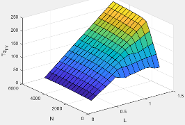
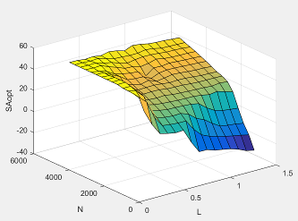
The optimal spark lookup table, , is a function of engine speed and engine load, , where:
SAopt is optimal spark advance timing for maximum inner torque at stoichiometric air-fuel ratio (AFR), in deg.
L is engine load at arbitrary cam phaser angles, corrected for final steady-state cam phaser angles, dimensionless.
N is engine speed, in rpm.
Dependencies
To enable this parameter, for the Torque model parameter,
select Torque Structure.
Inner torque load breakpoints, dimensionless.
Dependencies
To enable this parameter, for the Torque model parameter,
select Torque Structure.
Inner torque speed breakpoints, in rpm.
Dependencies
To enable this parameter, for the Torque model parameter,
select Torque Structure.
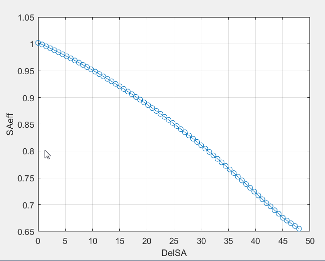
The spark efficiency lookup table, , is a function of the spark retard from optimal
where:
is the spark retard efficiency multiplier, dimensionless.
is the spark retard timing distance from optimal spark advance, in deg.
Dependencies
To enable this parameter, for the Torque model parameter,
select Torque Structure.
Spark retard from optimal inner torque timing breakpoints, in deg.
Dependencies
To enable this parameter, for the Torque model parameter,
select Torque Structure.
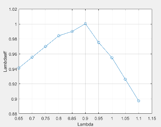
The lambda efficiency lookup table, , is a function of lambda, , where:
is the lambda multiplier on inner torque to account for the air-fuel ratio (AFR) effect, dimensionless.
is lambda, AFR normalized to stoichiometric fuel AFR, dimensionless.
Dependencies
To enable this parameter, for the Torque model parameter,
select Torque Structure.
Lambda effect on inner torque lambda breakpoints, dimensionless.
Dependencies
To enable this parameter, for the Torque model parameter,
select Torque Structure.
Exhaust
The exhaust temperature lookup table, , is a function of engine load and engine speed
where:
Texh is engine exhaust temperature, in K.
L is normalized cylinder air mass or engine load, dimensionless.
N is engine speed, in rpm.
Programmatic Use
To set the block parameter value programmatically, use
the set_param function.
To get the block parameter value
programmatically, use the get_param function.
| Parameter: | f_t_exh |
| Values: | array |
| Data Types: | double |
Engine speed breakpoints used for exhaust temperature lookup table, in rpm.
Programmatic Use
To set the block parameter value programmatically, use
the set_param function.
To get the block parameter value
programmatically, use the get_param function.
| Parameter: | f_t_exh_n_bpt |
| Values: | vector |
| Data Types: | double |
References
[1] Gerhardt, J., Hönninger, H., and Bischof, H., A New Approach to Functional and Software Structure for Engine Management Systems — BOSCH ME7. SAE Technical Paper 980801, 1998.
[2] Heywood, John B. Internal Combustion Engine Fundamentals. New York: McGraw-Hill, 1988.
[3] Leone, T. Christenson, E., Stein, R., Comparison of Variable Camshaft Timing Strategies at Part Load. SAE Technical Paper 960584, 1996, doi:10.4271/960584.
[4] Liu, F. and Pfeiffer, J., Estimation Algorithms for Low Pressure Cooled EGR in Spark-Ignition Engines. SAE Int. J. Engines 8(4):2015, doi:10.4271/2015-01-1620.
Extended Capabilities
Version History
Introduced in R2017a