SI Engine Dual-Independent Cam Phaser Air Mass Flow Model
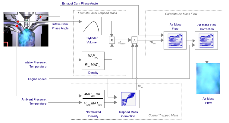
To calculate intake air mass flow for an engine equipped with cam phasers, you can configure the spark-ignition (SI) engine with a dual-independent cam phaser intake air mass flow model. As illustrated, the spark-ignition (SI) engine intake air mass flow calculation consists of these steps:
Collecting physical measurements
Estimating the ideal trapped mass
Correcting the trapped mass
Calculating the intake air mass flow
The dual-independent cam phaser intake air mass flow model implements equations that use these variables.
|
Estimated ideal trapped mass | |
|
Trapped mass correction multiplier | |
|
Flow rate equivalent to corrected trapped mass at the current engine speed | |
|
Engine intake air mass flow at arbitrary cam phaser angles | |
|
Engine intake port mass flow at arbitrary cam phaser angles | |
|
Engine intake air mass flow final correction at steady-state cam phaser angles | |
|
Engine intake port mass flow at steady-state cam phaser angles | |
|
Engine intake manifold air mass fraction | |
|
Intake manifold pressure at IVC | |
|
Intake manifold temperature at IVC | |
|
Nominal engine cylinder intake air mass at standard temperature and pressure, piston at bottom dead center (BDC) maximum volume | |
|
Intake air temperature | |
|
Engine speed | |
|
Number of engine cylinders | |
|
Cylinder volume at IVC | |
|
Displaced volume | |
|
Ideal gas constant | |
|
Ambient pressure | |
|
Standard temperature | |
|
Standard pressure | |
|
Normalized density | |
|
Measured intake cam phaser angle | |
|
Exhaust cam phaser angle | |
|
Engine load (normalized cylinder air mass) at arbitrary cam phaser angles, uncorrected for final steady-state cam phaser angles | |
|
Engine load (normalized cylinder air mass) at arbitrary cam phaser angles, corrected for final steady-state cam phaser angles | |
|
Crankshaft revolutions per power stroke | |
|
Cylinder volume at IVC table | |
|
Trapped mass correction table | |
|
Intake air mass flow table | |
|
Intake air mass flow correction table |
Collect Physical Measurements
In the SI engine model, the dual-independent cam phaser intake air mass flow model requires these physical measurements:
Intake manifold temperature and pressure at intake valve closing (IVC) condition
Intake cam phase angle
Exhaust cam phase angle
Engine speed
Ambient pressure and temperature
Intake air mass flow, from one or more of the following
Tank air meter
Wide range air-fuel sensor and fuel-flow meter
Wide range air-fuel sensor and injector pulse-width
Estimate Ideal Trapped Mass
The dual-independent cam phaser intake air mass flow model uses the Ideal Gas Law to estimate the ideal trapped mass at intake manifold conditions. The calculation assumes the cylinder pressure and temperature at IVC equal the intake manifold pressure and temperature.
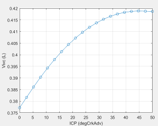
For engines with variable intake cam phasing, the trapped volume at IVC varies.
The cylinder volume at intake valve close table (IVC), is a function of the intake cam phaser angle
where:
is cylinder volume at IVC, in L.
is intake cam phaser angle in crank degrees of advance relative to the intake phaser park position.
Correct Trapped Mass
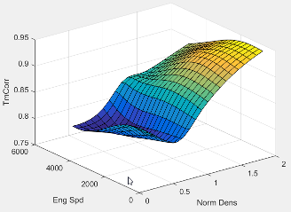
The dual-independent cam phaser intake air mass flow model uses a correction factor to account for the difference between the ideal trapped mass in the cylinder and the actual trapped mass. The trapped mass correction factor is a lookup table that is a function of the normalized density and engine speed.
The trapped mass correction factor table, , is a function of the normalized density and engine speed
where:
, is trapped mass correction multiplier, dimensionless.
is normalized density, dimensionless.
N is engine speed, in rpm.
Normalized density accounts for the throttle position independent of a given altitude.
Engine speed accounts for the pulsation effects of the piston movement.
Ambient pressure is measured by a sensor on the electronic control unit (ECU) or estimated using an inverse throttle valve model.
The ECU estimates or measures intake air temperature (IAT) upstream of the throttle.
Trapped mass flow is expressed as a flow rate in grams per second (g/s). The trapped mass flow is the maximum gas mass flow through the engine when no residual gases remain in the cylinder at the end of the exhaust stroke.
Calculate Air Mass Flow
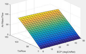
To determine the engine intake air mass flow at arbitrary cam phase angles, the dual-independent cam phaser air mass flow model uses a lookup table.
The phaser intake mass flow model lookup table is a function of exhaust cam phaser angles and trapped air mass flow
where:
is engine intake port mass flow at arbitrary cam phaser angles, in g/s.
is exhaust cam phaser angle in crank degrees of retard relative to the exhaust phaser park position.
is flow rate equivalent to corrected trapped mass at the current engine speed, in g/s.
The exhaust cam phasing has a significant effect on the fraction of burned gas. During the exhaust stroke, exhaust cam-phasing affects the exhaust valve position at exhaust valve closing (EVC) relative to the piston position. A retarded (late) exhaust cam phase angle moves EVC past piston top dead center (TDC), causing the exhaust gas to flow back from the manifold runner into the cylinder. This pull-back triggers the reburn of crevice volume gasses, reducing nitric oxide and nitrogen dioxide emissions (NOx) via charge temperature reduction and hydrocarbon (HC) emissions. Exhaust temperature and back pressure affect exhaust gas back-flow and exhaust cam phaser timing. Exhaust gas temperature and pressure correlate to trapped mass flow. Since at least 80% of trapped mass flow is unburned air, air mass flow is highly correlated to trapped mass flow.
The unburned air mass flow determines the engine load and open-loop fuel control to achieve a target air-fuel ratio (AFR).
The lookup table allows arbitrary cam phaser position combinations that can occur during transient engine operations when the phasers are moving from one target position to another.
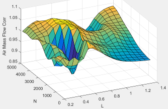
The intake air mass flow correction lookup table, , is a function of ideal load and engine speed
where:
is engine load (normalized cylinder air mass) at arbitrary cam phaser angles, uncorrected for final steady-state cam phaser angles, dimensionless.
N is engine speed, in rpm.
is engine intake air mass flow final correction at steady-state cam phaser angles, in g/s.
is engine intake port mass flow at arbitrary cam phaser angles, in g/s.
To calculate the engine intake port mass flow, the engine model uses this equation.
Ideal load is the normalized engine cylinder unburned intake air mass before the final correction. To calculate ideal load, the model divides the unburned intake air mass by the nominal cylinder intake air mass. The nominal cylinder intake air mass is the intake air mass (kg) in a cylinder at piston bottom dead center (BDC) with air at standard temperature and pressure:
The final engine load is expressed by
See Also
SI Controller | SI Core Engine