주요 콘텐츠

patternFromAI

R2026b

Reconstruct 3-D radiation pattern of antenna or array using AI

Since R2024a

    Description

    Note

    To use the patternFromAI function, you need a Deep Learning Toolbox™ license in addition to the Antenna Toolbox™ license.

    To reconstruct a pattern from sparse input data, or to specify the NumSteps name-value argument, you must also download and install the Machine Learning Models for Antenna Toolbox support package. You can also interactively install the support package using the Add-Ons panel. Reconstruction from two orthogonal slices does not require the support package.

    patternFromAI(magVertSlice, angleVertSlice, magHorizSlice, angleHorizSlice) plots the approximate 3-D radiation pattern reconstructed from the magnitude and angle data of input orthogonal slices vertslice and horizSlice.

    example

    [p3D, vertAngleOut, horizAngleOut] = patternFromAI(___) returns the reconstructed pattern as a matrix along with the vectors of the horizontal and vertical angle values in degrees. For the matrix p3D, the number of rows/columns correspond to the number of elements of horizAngleOut/vertAngleOut.

    p3D = patternFromAI(data, angle1, angle2) reconstructs the 3-D radiation pattern from sparse magnitude samples data specified at the sample angles angle1 and angle2, and returns the pattern as the matrix p3D. Use this syntax to reconstruct a pattern from irregularly sampled data instead of two orthogonal slices.

    This syntax requires the Machine Learning Models for Antenna Toolbox support package.

    [p3D, vertAngleOut, horizAngleOut] = patternFromAI(data, angle1, angle2) also returns the vectors of vertical and horizontal angle values in degrees.

    This syntax requires the Machine Learning Models for Antenna Toolbox support package.

    [___] = patternFromAI(___,Name=Value) specifies customization and tuning options, such as the angle convention, additional minimum and maximum magnitudes for slice normalization, and pattern plot options using one or more name-value arguments.

    Examples

    collapse all

    This example shows how to reconstruct the 3-D radiation pattern of a dipole antenna operating at 70 MHz from its two orthogonal slices.

    Get 2-D Pattern Data of Dipole Antenna

    Define the azimuth and elevation angle ranges. Get the azimuth pattern data at 0∘ elevation. Visualize the azimuth pattern.

    az = 0:359;
    el = -180:179;
    pA = patternAzimuth(dipole,70e6,0,Azimuth=az);
    figure
    patternAzimuth(dipole,70e6,0,Azimuth=az)
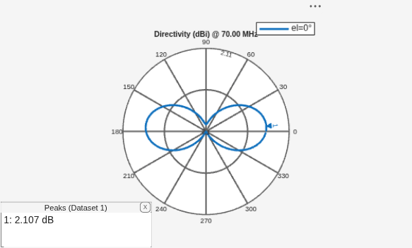
    Figure contains an axes object and an object of type uicontainer. The hidden axes object contains 2 objects of type line, text. This object represents el=0° .

    Get the elevation pattern data at 0∘ azimuth. Visualize the elevation pattern.

    pE = patternElevation(dipole,70e6,0,Elevation=el);
    figure
    patternElevation(dipole,70e6,0,Elevation=el)
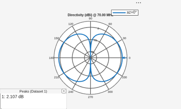
    Figure contains an axes object and an object of type uicontainer. The hidden axes object contains 2 objects of type line, text. This object represents az=0° .

    Reconstruct 3-D Radiation Pattern of Dipole Antenna

    Use patternFromAI function to reconstruct the 3-D radiation pattern. Visualize the 3-D pattern.

    theta = 90-el;
    phi = az;
    [p3D, vertAngleOut, horizAngleOut] = patternFromAI(pE,theta,pA,phi);
    figure
    patternFromAI(pE,theta,pA,phi)
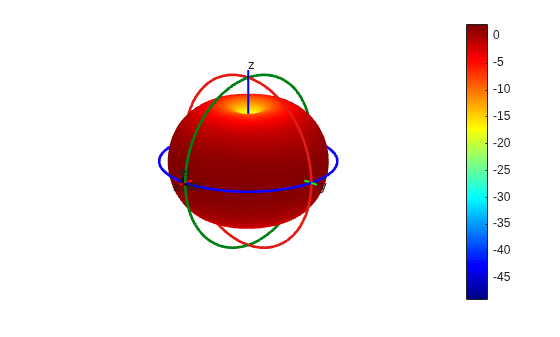
    Figure contains an axes object. The hidden axes object contains 16 objects of type surface, line, text, patch.

    This example shows how to import 2-D pattern data from a .pln file and reconstruct the 3-D radiation pattern from it.

    Import 2-D Pattern Data

    Use the msiread function to read a .pln file and import its contents to the workspace. Extract the magnitude and angles data form the workspace variables.

    [Horizontal,Vertical] = msiread('Test_file_demo.pln');
    pE = Vertical.Magnitude;
    el = Vertical.Elevation;
    pA = Horizontal.Magnitude;
    az = Horizontal.Azimuth;

    Plot the elevation cut.

    figure 
    polarpattern(Vertical.Elevation,Vertical.Magnitude,TitleTop="Elevation Cut")
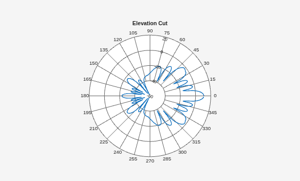
    Figure contains an axes object. The hidden axes object contains 2 objects of type line, text.

    Plot the azimuth cut.

    figure 
    polarpattern(Horizontal.Azimuth,Horizontal.Magnitude,TitleTop="Azimuthal Cut")
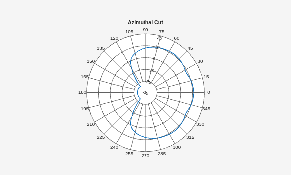
    Figure contains an axes object. The hidden axes object contains 2 objects of type line, text.

    Reconstruct 3-D Pattern

    Use the "az-el" angle convention to reconstruct the 3-D pattern from imported 2-D pattern magnitude and angle data.

    figure
    patternFromAI(pE,el,pA,az,AngleConvention="az-el")
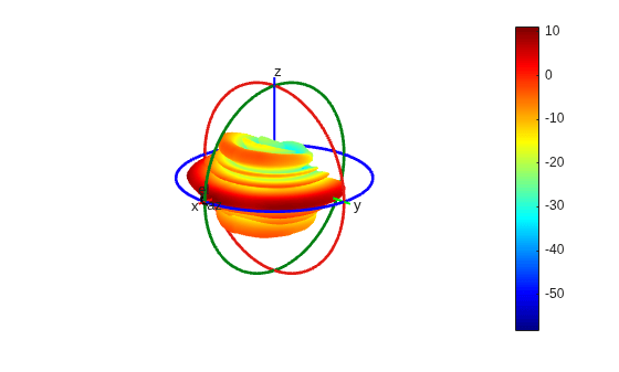
    Figure contains an axes object. The hidden axes object contains 16 objects of type surface, line, text, patch.

    Input Arguments

    collapse all

    2-D pattern slice magnitude data along vertical/elevation plane in dBi, specified as a real-valued vector of either 360 or 361 elements, sampled at 1 degree resolution.

    Example: [10.55 10.25 10 ... -2]

    Data Types: double

    Vertical/elevation slice angles in degrees, specified as a real-valued integer vector of either 360 or 361 elements, at 1 degree spacing.

    Example: 0:360

    Data Types: double

    2-D pattern slice magnitude data along horizontal/azimuth plane in dBi, specified as a real-valued vector of either 360 or 361 elements, sampled at 1 degree resolution.

    Example: [10.55 10.25 10 ... -2]

    Data Types: double

    Horizontal/azimuth slice angles in degrees, specified as a real-valued integer vector of either 360 or 361 elements, at 1 degree spacing.

    Example: 0:360

    Data Types: double

    Sparse pattern magnitude samples in dBi, specified as a real-valued vector. Each element is the directivity, in dBi, at the corresponding sample angles specified by angle1 and angle2. The vectors data, angle1, and angle2 must have the same number of elements. Use this argument to reconstruct a pattern from irregularly sampled data instead of two orthogonal slices.

    Example: [10.55 10.25 10 ... -2]

    Dependencies

    To reconstruct a pattern from sparse input data, you must download and install the Machine Learning Models for Antenna Toolbox support package.

    Data Types: double

    First angle coordinate of the sparse samples in degrees, specified as a real-valued vector with the same number of elements as data. The interpretation of angle1 depends on the AngleConvention name-value argument: it is the φ (phi) angle when AngleConvention is "phi-theta", and the azimuth angle when AngleConvention is "az-el".

    Example: [0 30 45 90 ... 360]

    Data Types: double

    Second angle coordinate of the sparse samples in degrees, specified as a real-valued vector with the same number of elements as data. The interpretation of angle2 depends on the AngleConvention name-value argument: it is the θ (theta) angle when AngleConvention is "phi-theta", and the elevation angle when AngleConvention is "az-el".

    Example: [90 90 60 30 ... 0]

    Data Types: double

    Name-Value Arguments

    collapse all

    Specify optional pairs of arguments as Name1=Value1,...,NameN=ValueN, where Name is the argument name and Value is the corresponding value. Name-value arguments must appear after other arguments, but the order of the pairs does not matter.

    Example: AngleConvention="az-el"

    Angle convention used in the input angles vertAngle and horizAngle for reconstruction, specified as either "phi-theta" or "az-el". The default angle convention is "phi-theta". For more information on angle conventions, see Antenna Toolbox Coordinate System.

    Example: "az-el"

    Data Types: string

    Magnitudes to normalize the input data, specified as a 2-element vector in dBi. The first element of the vector is the minimum magnitude and second element is the maximum magnitude. To specify only one element, assign the other as -Inf or Inf respectively.

    When you use the Machine Learning Models for Antenna Toolbox support package, the default is the model-trained normalization window [peak-60 peak], where peak is the maximum magnitude in the input data. In this case, Inf resolves to the observed maximum and -Inf resolves to 60 dB below the resolved maximum. For example, [-Inf 25] resolves to [-35 25], and [-Inf Inf] is equivalent to the default window.

    When the support package is not installed, patternFromAI uses the literal minimum and maximum values in the input slices, and finite values override the corresponding bound directly.

    Tip

    If the minimum and/or maximum directivity values of the pattern are known but are absent from the input data, specify either one or both in the MinMaxMagnitude argument to increase the accuracy of the pattern reconstruction.

    Example: [10 50]

    Data Types: double

    Plot visualization options, specified as a PatternPlotOptions object. Only the Transparency and MagnitudeScale properties of PatternPlotOPtions can be changed. The other two properties SizeRatio and AntennaOffset are ignored.

    Example: PatternPlotOptions(Transparency=0.6, MagnitudeScale=[1 10])

    Number of reverse diffusion steps used during reconstruction, specified as a positive integer in the range [1, 1000]. A larger value of NumSteps can improve reconstruction quality at the cost of longer computation time.

    Example: 50

    Dependencies

    This name-value argument requires the Machine Learning Models for Antenna Toolbox support package.

    Data Types: double

    Maximum spherical harmonic degree for angular smoothing, specified as a positive integer in the range [1, 90]. This argument applies an angular low-pass operation by truncating the spherical harmonic expansion of the reconstructed pattern to degree MaxDegree. A smaller value produces smoother, more global angular structure, and a larger value preserves sharper lobes, narrower nulls, and finer angular detail. Use a smaller value to suppress small-scale artifacts or noise, and a larger value to preserve localized angular features. If you do not specify MaxDegree, the function does not apply angular smoothing and preserves all angular content that the output grid can represent.

    The output grid must be able to represent the requested degree, so both output angular dimensions must support at least 2*MaxDegree + 1 samples. If the requested degree is not supported by the output grid, patternFromAI clamps the degree to the largest supported value and issues a warning.

    Example: 20

    Data Types: double

    Rotation angle of the reconstructed pattern in degrees, specified as a real scalar or a real vector. The pattern is rotated on the sphere about the axis specified by the TiltAxis name-value argument. When you specify a vector, the rotations are applied in sequence. Rotation alone does not apply angular smoothing and preserves all angular content the output grid can represent. When you specify both Tilt and MaxDegree, the pattern is smoothed to the requested degree and then rotated in spherical harmonic coefficient space. If you do not specify Tilt, the function does not rotate the reconstructed pattern.

    Example: 30

    Data Types: double

    Axis of rotation for the reconstructed pattern, specified as "X", "Y", "Z", or a three-element vector [x y z] that defines the axis direction. When you specify Tilt as a vector, specify TiltAxis as a matrix with one axis per row, matching the number of tilt angles. Use this argument together with the Tilt name-value argument. When you specify Tilt but not TiltAxis, the function rotates the pattern about the z-axis. This argument has no effect if you do not specify Tilt.

    Example: "Y"

    Data Types: string | double

    Output Arguments

    collapse all

    3-D pattern magnitude data in dBi, returned as a 360-by-181 real matrix on an equiangular grid with no duplicated azimuth (φ) seam. The number of rows equals the number of elements of horizAngleOut, and the number of columns equals the number of elements of vertAngleOut.

    Data Types: double

    Vertical or elevation angles in degrees, returned as a 181-by-1 real integer vector. When AngleConvention is "phi-theta", the angles are the θ (theta) values returned in descending order from 180 to 0. When AngleConvention is "az-el", the angles are the corresponding elevation values.

    Data Types: double

    Horizontal or azimuth angles in degrees, returned as a 360-by-1 real integer vector. When AngleConvention is "phi-theta", the angles are the φ (phi) values from 0 to 359. When AngleConvention is "az-el", the angles are the corresponding azimuth values.

    Data Types: double

    Version History

    Introduced in R2024a

    expand all