cavityCircular
Create circular cavity-backed antenna
Description
The default cavityCircular object creates a circular
cavity-backed antenna resonating around 833 MHz. By default, a dipole element is used as
an exciter for this antenna. The feed point is located on the exciter.
.
Creation
Description
c = cavityCircular
c = cavityCircular(PropertyName=Value)PropertyName is the property name and
Value is the corresponding value. You can specify
several name-value arguments in any order as
PropertyName1=Value1,...,PropertyNameN=ValueN.
Properties not specified retain their default values.
For example, c = cavityCircular(Radius=0.2) creates a
circular-cavity backed antenna with cavity radius of 0.2 m. and default
values for other properties.
Properties
Object Functions
axialRatio | Calculate and plot axial ratio of antenna or array |
bandwidth | Calculate and plot absolute bandwidth of antenna or array |
beamwidth | Beamwidth of antenna |
charge | Charge distribution on antenna or array surface |
current | Current distribution on antenna or array surface |
design | Create antenna, array, or AI-based antenna resonating at specified frequency |
efficiency | Calculate and plot radiation efficiency of antenna or array |
EHfields | Electric and magnetic fields of antennas or embedded electric and magnetic fields of antenna element in arrays |
feedCurrent | Calculate current at feed for antenna or array |
impedance | Calculate and plot input impedance of antenna or scan impedance of array |
info | Display information about antenna, array, or platform |
memoryEstimate | Estimate memory required to solve antenna or array mesh |
mesh | Generate and view mesh for antennas, arrays, and custom shapes |
meshconfig | Change meshing mode of antenna, array, custom antenna, custom array, or custom geometry |
msiwrite | Write antenna or array analysis data to MSI planet file |
optimize | Optimize antenna and array catalog elements using SADEA or TR-SADEA algorithm |
pattern | Plot radiation pattern of antenna, array, or embedded element of array |
patternAzimuth | Azimuth plane radiation pattern of antenna or array |
patternElevation | Elevation plane radiation pattern of antenna or array |
peakRadiation | Calculate and mark maximum radiation points of antenna or array on radiation pattern |
rcs | Calculate and plot monostatic and bistatic radar cross section (RCS) of platform, antenna, or array |
resonantFrequency | Calculate and plot resonant frequency of antenna |
returnLoss | Calculate and plot return loss of antenna or scan return loss of array |
show | Display antenna, array, AI-based antenna, platform, or shape |
sparameters | Calculate S-parameters for antenna or array |
stlwrite | Write mesh information to STL file |
vswr | Calculate and plot voltage standing wave ratio (VSWR) of antenna or array element |
Examples
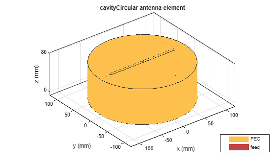
Create and view a default circular cavity-backed antenna.
a = cavityCircular
a =
  cavityCircular with properties:

            Exciter: [1×1 dipole]
          Substrate: [1×1 dielectric]
             Radius: 0.1000
             Height: 0.0750
            Spacing: 0.0750
    EnableProbeFeed: 0
          Conductor: [1×1 metal]
               Tilt: 0
           TiltAxis: [1 0 0]
               Load: [1×1 lumpedElement]
show(a)
Create and view an equiangular spiral backed by a circular cavity. The cavity dimensions are:
Radius = 0.02 m
Height = 0.01 m
Spacing = 0.01 m
 ant = cavityCircular(Exciter=spiralEquiangular,Radius=0.02,   ...
          Height=0.01,Spacing=0.01);
show(ant) 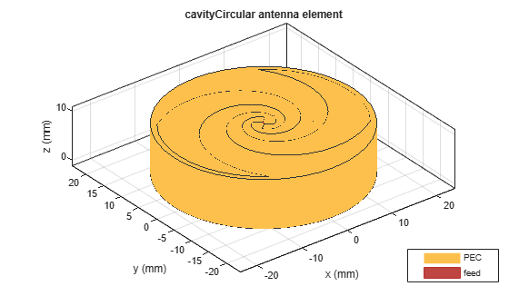
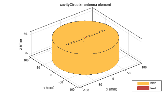
Create a linear array of H-shaped patch microstrip antenna.
arr = linearArray(Element=patchMicrostripHnotch,ElementSpacing=0.04);
Create a circular cavity-backed antenna with linear array exciter.
ant = cavityCircular(Exciter=arr)
ant =
  cavityCircular with properties:

            Exciter: [1×1 linearArray]
          Substrate: [1×1 dielectric]
             Radius: 0.1000
             Height: 0.0750
            Spacing: 0.0750
    EnableProbeFeed: 0
          Conductor: [1×1 metal]
               Tilt: 0
           TiltAxis: [1 0 0]
               Load: [1×1 lumpedElement]
show(ant)

Create and visualize a circular cavity-backed cylindrical dielectric resonator antenna.
e = draCylindrical;
ant = cavityCircular(Exciter=e)
ant =
  cavityCircular with properties:

            Exciter: [1×1 draCylindrical]
          Substrate: [1×1 dielectric]
             Radius: 0.1000
             Height: 0.0750
            Spacing: 0.0750
    EnableProbeFeed: 0
          Conductor: [1×1 metal]
               Tilt: 0
           TiltAxis: [1 0 0]
               Load: [1×1 lumpedElement]
show(ant)

This example shows how to create a circular cavity structure as an element in a conformalArray and plot its surface current distribution.
Create Circular Cavity Antenna
Create a circular cavity antenna operating at 1 GHz using the design function and the cavityCircular element from the antenna catalog. Display the antenna.
f = 1e9;
lambda = 3e8/f;
ant = design(cavityCircular,f);
figure
show(ant)
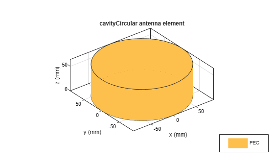
Derive Backing Structure
Derive the circular cavity backing structure from the cavity antenna by specifying the 'Exciter' property as an empty array. Display the backing structure.
ant.Exciter = [];
figure
show(ant)
Create Conformal Array
Create and display a conformal array with circular cavity as one of its elements.
ca = conformalArray;
ca.Reference = "origin";
ca.ElementPosition = [0 0 0; 0 0 0.25; 0 0 0.5];
ca.Element = {ca.Element{1} ant ca.Element{2}};
figure
show(ca)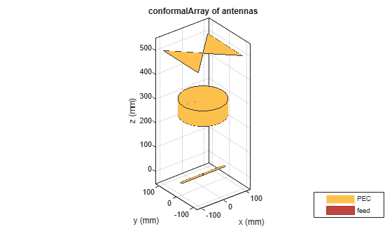
Plot Surface Current Distribution
Calculate the current at the feed location and plot the surface current distribution of the conformal array at 1 GHz.
If = feedCurrent(ca,f)
If = 1×2 complex

   0.0023 - 0.0005i   0.0029 + 0.0007i
figure
current(ca,f,Scale="log10")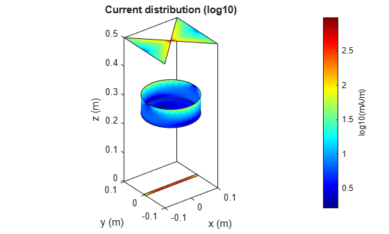
Version History
Introduced in R2017b