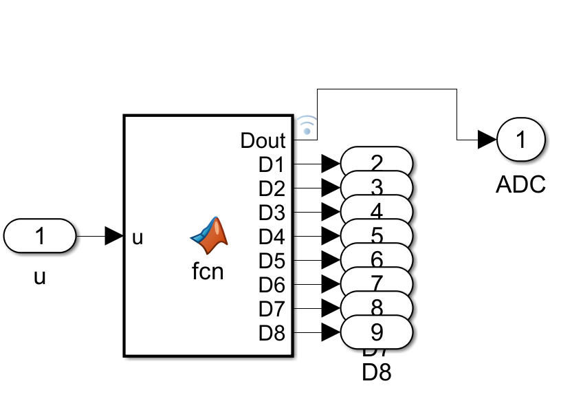
The diagram represents a Simulink model (possibly for digital signal processing or embedded systems simulation). Here’s a step-by-step explanation:
- Input ('u'): The model receives an input signal labeled as 'u' (with a value of 1 in this instance).
- MATLAB Function Block ('fcn'): The input 'u' is fed into a MATLAB Function block, which processes the input using a custom function ('fcn'). The function block outputs 8 digital signals labeled as `D1` to `D8` (collectively `Dout`).
- Digital Output Ports ('D1' to 'D8'): Each output from the function block is routed to a corresponding digital output port (numbered 2 to 9).
- ADC Block: The outputs from the digital ports are then combined and fed into an ADC (Analog-to-Digital Converter) block. The ADC output is labeled as '1'.
This model demonstrates the process of converting an analog signal into digital form using MATLAB/Simulink and visualizes the individual digital bits.