DVB-S2X LDPC Decoder
R2026bDVB-S2X LDPC Decoder block
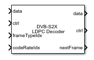
To add a block to a model, double-click the canvas and start typing the block name. Then, select the block from the list.
Libraries:
Wireless HDL Toolbox /
Error Detection and Correction
Description
The DVB-S2X LDPC Decoder block implements a low-density parity-check (LDPC) decoder using layered belief propagation with min-sum approximation and normalized min-sum approximation algorithms for decoding LDPC codes according to the Digital Video Broadcasting Satellite Second Generation (DVB-S2X) standard. The block accepts log-likelihood ratio (LLR) values, a stream of control signals, a frame type, and a code rate as inputs and outputs decoded bits, a stream of control signals, and a signal that indicates when the block is ready to accept new inputs.
The DVB-S2X LDPC Decoder block supports early termination to help improve decoding performance and convergence speeds at high signal-to-noise-ratio (SNR) conditions. The block supports parallelism at two levels 45 and 180. The block supports scalar and vector values through the input/output (I/O) interface. It also supports forward error correction (FEC) frames of type normal, short, and medium with all the code rates supported by the DVB-S2X standard. For more information about the DVB-S2X standard, see [1].
The block provides an architecture suitable for HDL code generation and hardware deployment.
Examples
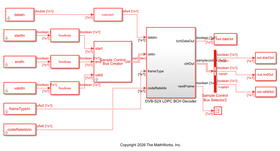
Decode and Recover Message Using DVB-S2X Standard FEC Decoder
Decode and recover message from codeword using FEC decoder according to DVB-S2X standard.
Ports
Input
Output
Parameters
Algorithms
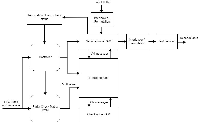
This figure shows the architecture block diagram of the DVB-S2X LDPC Decoder block. The Controller block controls the layer and iteration count of the decoding process. The Variable node RAM block stores the variable node (VN) messages, and the Check node RAM block stores the check node (CN) messages. The block reads data from the Variable Node RAM continuously on a row-by-row basis and applies parity-check matrix transformations, such as column and row interchanges, to avoid memory conflicts between consecutive rows. When memory conflicts still occur, the block introduces a small delay between row updates to ensure correct operation. The Functional Unit block calculates the VN messages and CN messages based on layered belief propagation and either the normalized min-sum approximation algorithm or the min-sum approximation algorithm. When you select the Normalized Min-sum algorithm, the block applies a scaling factor to the CN updates. The Termination/Parity check status block calculates the parity checks and provides the parity check status after each iteration. The block processes multiple LLR samples per clock cycle based on the selected parallelism to improve throughput. For more information about decoding algorithms, see the following sections.
The latency of the block varies based on the input type, frame type, code rate, parallelism level, and number of iterations.
The latency of the block is equal to (r x t) +
d + inputLen. In this calculation, r is the number of iterations,
t is the number of clocks required to decode one iteration,
d is the pipeline delays, which are a fixed value equal to 18, and
inputLen is the length of the input data.
The table shows the number of clocks the block requires to decode one iteration for normal and short frame types with different code rates and parallelism levels.
| Code Rate Index | Number of Clocks Per Iteration for Parallelism 45 | Number of Clocks Per Iteration for Parallelism 180 | ||||
|---|---|---|---|---|---|---|
| Normal | Short | Medium | Normal | Short | Medium | |
| 0 | 5579 | 1626 | 2316 | 2763 | 693 | 1445 |
| 1 | 6740 | 1527 | 2188 | 2539 | 592 | 1316 |
| 2 | 6485 | 1756 | 2413 | 2231 | 612 | 1306 |
| 3 | 6126 | 1820 | Code rate not supported for medium frame | 1890 | 666 | Code rate not supported for medium frame |
| 4 | 7039 | 2009 | 2070 | 716 | ||
| 5 | 5329 | 1583 | 1453 | 627 | ||
| 6 | 5056 | 1374 | 1437 | 412 | ||
| 7 | 5200 | 1057 | 1413 | 324 | ||
| 8 | 5332 | 1229 | 1587 | 362 | ||
| 9 | 4351 | 1113 | 1170 | 312 | ||
| 10 | 4350 | 1100 | 1155 | 728 | ||
| 11 | 4492 | 1333 | 2889 | 758 | ||
| 12 | 5133 | 1253 | 2701 | 757 | ||
| 13 | 5559 | 1745 | 2018 | 847 | ||
| 14 | 5776 | 1698 | 1875 | 715 | ||
| 15 | 6065 | 1538 | 1743 | 545 | ||
| 16 | 5849 | 1369 | 1823 | 459 | ||
| 17 | 5777 | Code rate not supported for short frame | 1716 | Code rate not supported for short frame | ||
| 18 | 6098 | 1704 | ||||
| 19 | 6098 | 1837 | ||||
| 20 | 6355 | 1918 | ||||
| 21 | 5458 | 1640 | ||||
| 22 | 5218 | 1567 | ||||
| 23 | 6162 | 1721 | ||||
| 24 | 6736 | 1867 | ||||
| 25 | 6288 | 1695 | ||||
| 26 | 5737 | 1564 | ||||
| 27 | 6255 | 1678 | ||||
| 28 | 5616 | 1518 | ||||
| 29 | 6158 | 1645 | ||||
| 30 | 6541 | 1740 | ||||
| 31 | 6133 | 1632 | ||||
| 32 | 6412 | 1691 | ||||
| 33 | 5774 | 1533 | ||||
| 34 | 6270 | 1641 | ||||
This figure shows a Logic Analyzer waveform of the sample output and latency of the
DVB-S2X LDPC Decoder block for a scalar input when you set the
FEC frame type and Code rate values to
Normal and 90/180, respectively.
The latency of the block is 1,11,133 cycles.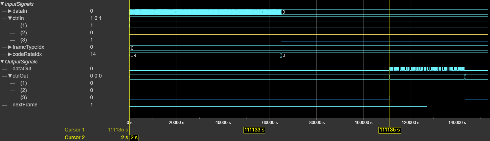
The latency of the block is equal to (r x t) +
d + inputLen. In this calculation, r is the number of iterations,
t is the number of clocks required to decode one iteration,
d is the pipeline delays, and inputLen is the
length of the input data.
The table shows the number of clocks the block requires to decode one iteration for normal and short frame types with different code rates and parallelism levels.
| Code Rate Index | Number of Clocks Per Iteration for Parallelism 45 | Number of Clocks Per Iteration for Parallelism 180 | ||||
|---|---|---|---|---|---|---|
| Normal | Short | Medium | Normal | Short | Medium | |
| 0 | 5579 | 1626 | 2316 | 2763 | 693 | 1445 |
| 1 | 6740 | 1527 | 2188 | 2539 | 592 | 1316 |
| 2 | 6485 | 1756 | 2413 | 2231 | 612 | 1306 |
| 3 | 6126 | 1820 | Code rate not supported for medium frame | 1890 | 666 | Code rate not supported for medium frame |
| 4 | 7039 | 2009 | 2070 | 716 | ||
| 5 | 5329 | 1583 | 1453 | 627 | ||
| 6 | 5056 | 1374 | 1437 | 412 | ||
| 7 | 5200 | 1057 | 1413 | 324 | ||
| 8 | 5332 | 1229 | 1587 | 362 | ||
| 9 | 4351 | 1113 | 1170 | 312 | ||
| 10 | 4350 | 1100 | 1155 | 728 | ||
| 11 | 4492 | 1333 | 2889 | 758 | ||
| 12 | 5133 | 1253 | 2701 | 757 | ||
| 13 | 5559 | 1745 | 2018 | 847 | ||
| 14 | 5776 | 1698 | 1875 | 715 | ||
| 15 | 6065 | 1538 | 1743 | 545 | ||
| 16 | 5849 | 1369 | 1823 | 459 | ||
| 17 | 5777 | Code rate not supported for short frame | 1716 | Code rate not supported for short frame | ||
| 18 | 6098 | 1704 | ||||
| 19 | 6098 | 1837 | ||||
| 20 | 6355 | 1918 | ||||
| 21 | 5458 | 1640 | ||||
| 22 | 5218 | 1567 | ||||
| 23 | 6162 | 1721 | ||||
| 24 | 6736 | 1867 | ||||
| 25 | 6288 | 1695 | ||||
| 26 | 5737 | 1564 | ||||
| 27 | 6255 | 1678 | ||||
| 28 | 5616 | 1518 | ||||
| 29 | 6158 | 1645 | ||||
| 30 | 6541 | 1740 | ||||
| 31 | 6133 | 1632 | ||||
| 32 | 6412 | 1691 | ||||
| 33 | 5774 | 1533 | ||||
| 34 | 6270 | 1641 | ||||
The table shows the number of pipeline delays for normal and short frame types with different code rates and parallelism levels.
| Code Rate Index | Number of Pipeline Delays for Parallelism 45 | Number of Pipeline Delays for Parallelism 180 | ||||
|---|---|---|---|---|---|---|
| Normal | Short | Medium | Normal | Short | Medium | |
| 0 | 1526 | 437 | 833 | 1519 | 430 | 826 |
| 1 | 1361 | 371 | 789 | 1354 | 364 | 782 |
| 2 | 1229 | 338 | 701 | 1222 | 331 | 694 |
| 3 | 1031 | 316 | Code rate not supported for medium frame | 1024 | 309 | Code rate not supported for medium frame |
| 4 | 833 | 239 | 826 | 232 | ||
| 5 | 701 | 206 | 694 | 199 | ||
| 6 | 536 | 173 | 529 | 166 | ||
| 7 | 437 | 151 | 430 | 144 | ||
| 8 | 371 | 129 | 364 | 122 | ||
| 9 | 261 | 96 | 254 | 89 | ||
| 10 | 239 | 415 | 232 | 408 | ||
| 11 | 1581 | 404 | 1574 | 397 | ||
| 12 | 1449 | 382 | 1442 | 375 | ||
| 13 | 1130 | 305 | 1123 | 298 | ||
| 14 | 1031 | 272 | 1024 | 265 | ||
| 15 | 965 | 250 | 958 | 243 | ||
| 16 | 932 | 184 | 925 | 177 | ||
| 17 | 921 | Code rate not supported for short frame | 914 | Code rate not supported for short frame | ||
| 18 | 877 | 870 | ||||
| 19 | 877 | 870 | ||||
| 20 | 833 | 826 | ||||
| 21 | 789 | 782 | ||||
| 22 | 756 | 749 | ||||
| 23 | 745 | 738 | ||||
| 24 | 701 | 694 | ||||
| 25 | 657 | 650 | ||||
| 26 | 646 | 639 | ||||
| 27 | 613 | 606 | ||||
| 28 | 591 | 584 | ||||
| 29 | 569 | 562 | ||||
| 30 | 569 | 562 | ||||
| 31 | 536 | 529 | ||||
| 32 | 481 | 474 | ||||
| 33 | 481 | 474 | ||||
| 34 | 327 | 320 | ||||
This figure shows a Logic Analyzer waveform of the sample output and latency of the
DVB-S2X LDPC Decoder block for a vector input when you set the
FEC frame type and Code rate values to
Normal and 90/180, respectively.
The latency of the block is 55,338 cycles.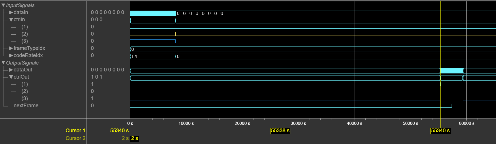
References
[1] ETSI Standard EN 302 307-2 V1.1.1: Digital Video Broadcasting (DVB); Second generation framing structure, channel coding and modulation systems for Broadcasting, Interactive Services, News Gathering and other broadband satellite applications, DVB-S2 Extensions (DVB-S2X),European Telecommunications Standards Institute, Valbonne, France, 2005-03.
[2] Gallager, R. “Low-Density Parity-Check Codes.” IEEE Transactions on Information Theory 8, no. 1 (January 1962): 21–28. https://doi.org/10.1109/TIT.1962.1057683.
[3] Hocevar, D.E. “A Reduced Complexity Decoder Architecture via Layered Decoding of LDPC Codes.” In IEEE Workshop On Signal Processing Systems, 2004. SIPS 2004, 107–12. Austin, Texas, USA: IEEE, 2004. https://doi.org/10.1109/SIPS.2004.1363033.
[4] Chen, Jinghu, R.M. Tanner, C. Jones, and Yan Li. "Improved Min-Sum Decoding Algorithms for Irregular LDPC Codes." In Proceedings. International Symposium on Information Theory, 2005. ISIT 2005. https://doi: 10.1109/ISIT.2005.1523374.
Extended Capabilities
Version History
Introduced in R2026b
See Also
DVB-S2X BCH Decoder | DVB-S2 LDPC Decoder | DVB-S2 BCH Decoder

