Set COM Port for Upload and Communication in Simulink
R2026bSimulink® automatically detects the correct COM port for Pixhawk® boards when uploading firmware and during host-target communication. If automatic detection fails for your board, use this page to identify the correct COM ports and manually configure them in Simulink.
Automatic COM Port Detection
On most Pixhawk boards, the COM port required to upload firmware (bootloader COM port) and the COM port required for MAVLink communication are the same. The Automatically determine serial port for firmware upload option in Simulink model settings detects the correct COM port.
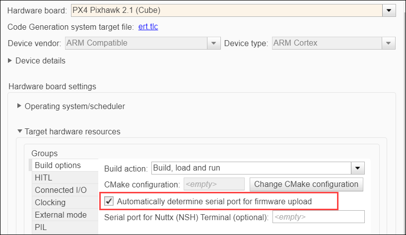
No additional settings are required in the External Mode, Connected I/O, or PIL tabs for the corresponding simulation modes.
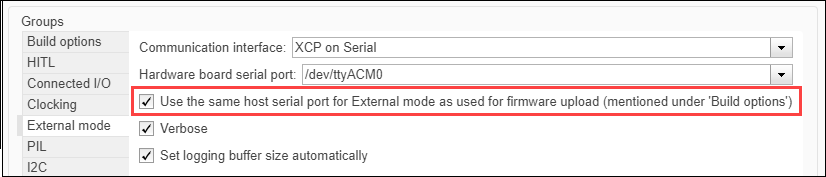
With automatic detection enabled, no additional configuration is needed even when the board has separate upload and communication ports.
Manually Set COM Port for Upload and Communication
If automatic COM port detection does not work for your board, clear the Automatically determine serial port for firmware upload option and manually configure the ports as described in the following sections.
Identify Bootloader and Communication COM Ports
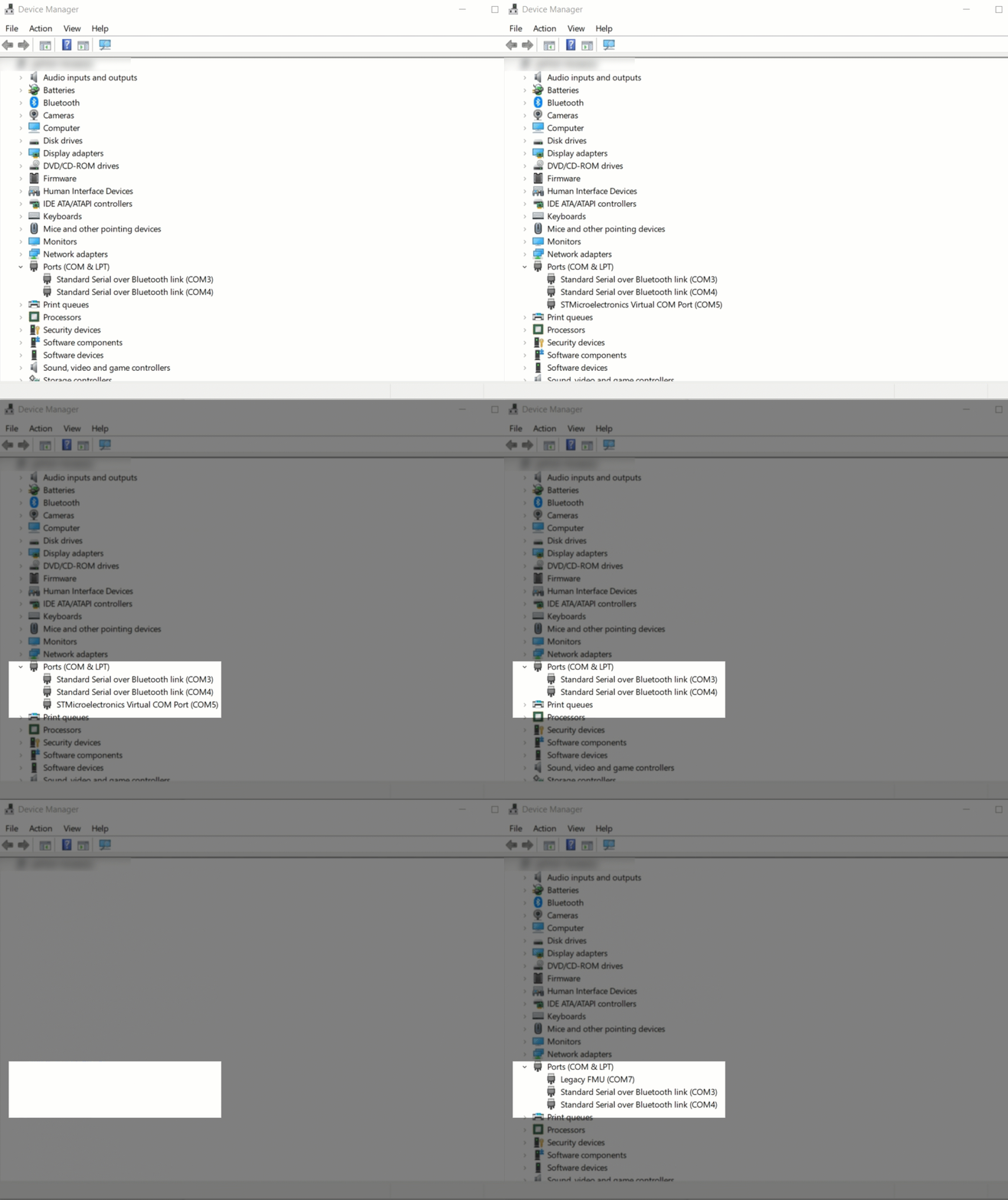
On some boards, the bootloader COM port for uploading firmware and the main communications COM port are different. When you connect to such boards, the bootloader port appears first in the Device Manager. The port shows for a few seconds and then the main communications port appears. Use the bootloader COM port for firmware upload and the communications port for MAVLink communication or Monitor and Tune simulation.
For example, the following animation shows the Device Manager window when a board with separate ports is connected. After connecting, the bootloader port appears under ports first. This port stays briefly, after which the board loads the main firmware and the main communication port appears.
Set Bootloader COM Port for Firmware Upload and Deployment
For the Simulink model, open the Hardware Settings.

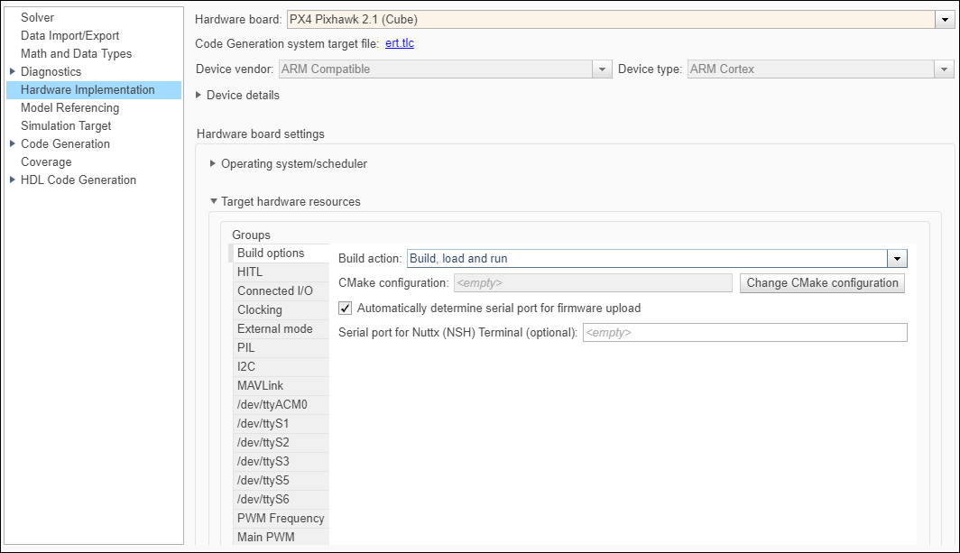
Clear the Automatically determine serial port for firmware upload option and enter the bootloader serial port in Serial Port for firmware upload.
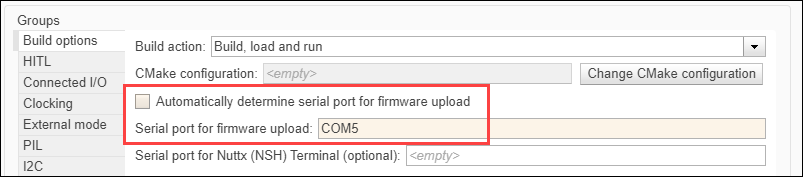
Deploy the Simulink model. On the Hardware tab, in the Mode section, select Run on board and then click Build, Deploy & Start.
Set Communication COM Port for Monitor & Tune (External Mode)
Perform the settings for Build options as shown in the topic Set Bootloader COM Port for Firmware Upload and Deployment.
In the External mode tab, clear the Use the same host serial port for External Mode as used for firmware upload option and enter the main communications port in Host Serial Port (this must be different from the bootloader port you specified in Build options).
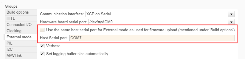
Run the model in External Mode.
Set Communication COM Port for PIL
Perform the settings for Build options as shown in the topic Set Bootloader COM Port for Firmware Upload and Deployment.
In the PIL tab, clear the Use the same host serial port for PIL as used for firmware upload option and enter the main communications port in Host Serial Port (this must be different from the bootloader port you specified in Build options).

Set Communication COM Port for Connected I/O
Perform the settings for Build options as shown in the topic Set Bootloader COM Port for Firmware Upload and Deployment.
In the Connected I/O tab, clear the Use the same host serial port for Connected I/O as used for firmware upload option and enter the main communications port in Host Serial Port (this must be different from the bootloader port you specified in Build options).


