Display Component Hierarchy and Architecture Hierarchy Using Views
This example shows how to visualize hierarchical relationships by using hierarchy views in the Architecture Views Gallery.
You can visualize a hierarchy diagram as a view with components, ports, reference types, component stereotypes, and stereotype properties. Component hierarchy diagrams display components in tree form with parents above children. In a component hierarchy view, each referenced model is represented as many times as it is used. Architecture hierarchy diagrams display unique component architecture types and their relationships using composition connections. In an architecture hierarchy view, each referenced model is represented only once.
For a roadmap of the views topics, see Create Custom Views Using Architecture Views Gallery.
Any component diagram view can be optionally represented as a hierarchy diagram. The hierarchy and component diagram views show the same set of components, and you select and filter components in the same way.
This example uses an architecture model representing data flow within a robotic system. Open this model to follow the steps in the tutorial.
Tip
To learn more about how System Composer™ concepts apply to systems engineering design, see System Composer Concepts.
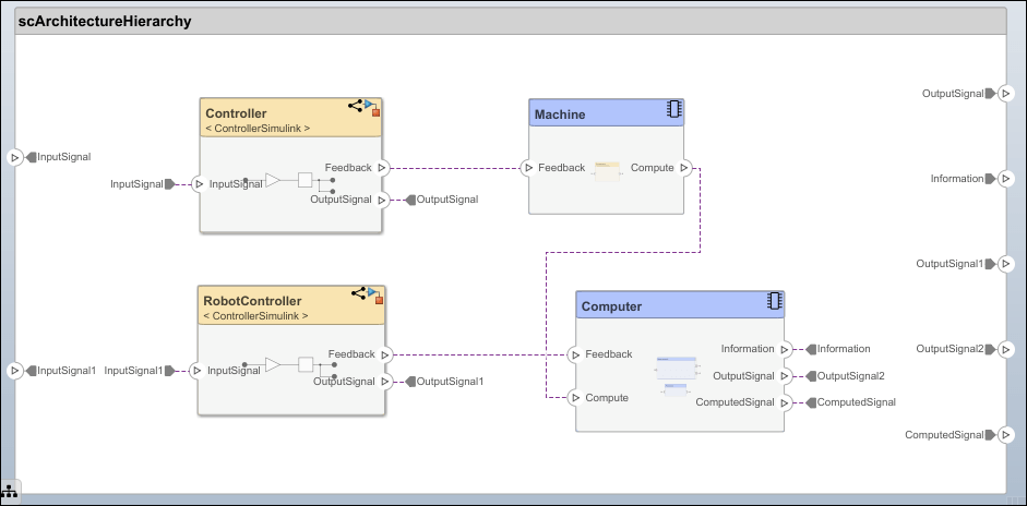
Robot Computer Systems Architecture
Use a robot computer system with controllers that simulate transmission of data to explore hierarchy diagrams in the Architecture Views Gallery.
Switch Between Component Diagram View and Hierarchy Views
Since R2021b
To open the Architecture Views Gallery, go to Modeling > Architecture Views.
In the View Browser, select the
All Componentsview.Observe the component diagram view that corresponds to the all the components in the architecture model.

The component diagram represents a view with components, ports, and connectors based on how the model is structured.
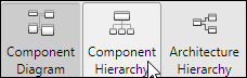
In the Diagram section of the toolstrip, click Component Hierarchy.
Observe the component hierarchy view that corresponds to the same set of components.
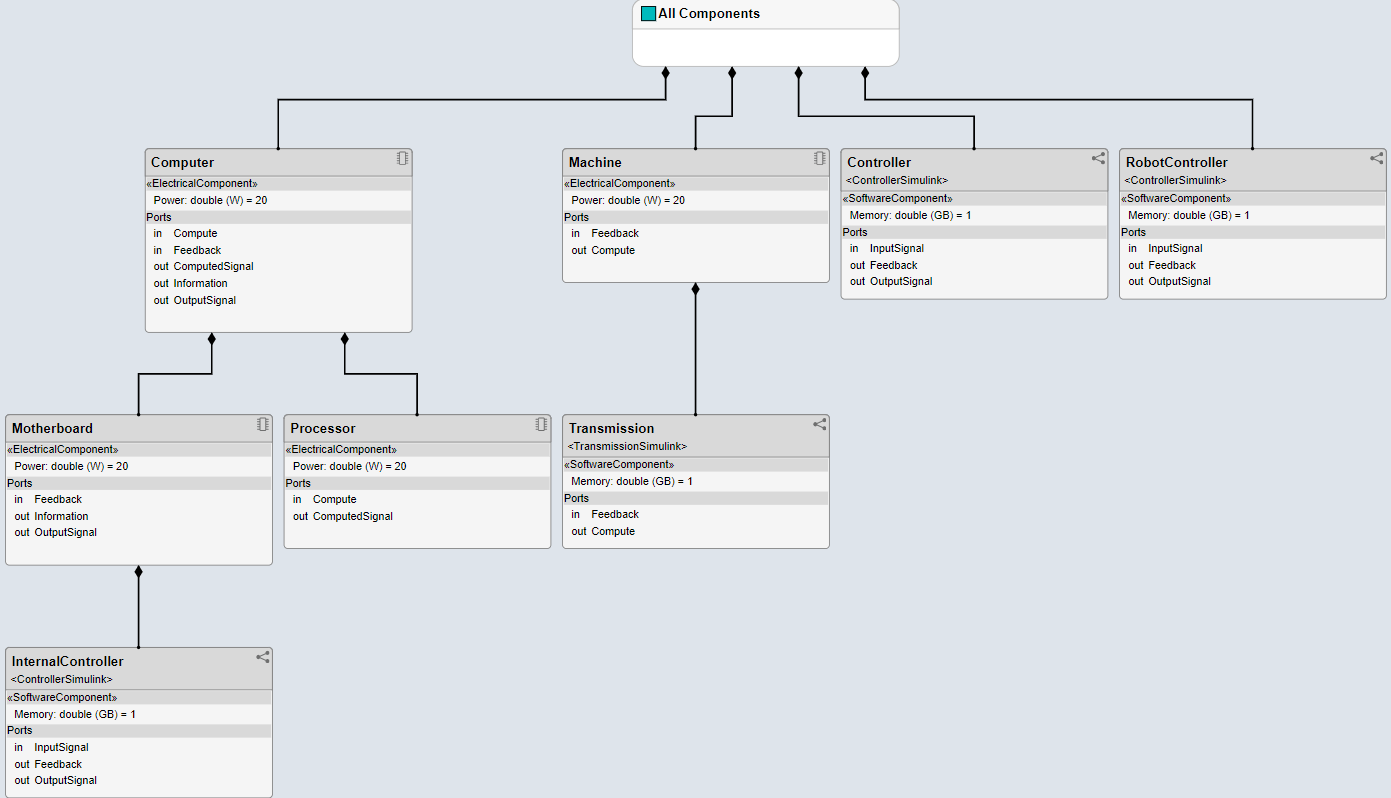
The component hierarchy diagram shows a single root, which is the view specification itself. The root corresponds to the name of the view shown in the component diagram. The connections in the component hierarchy diagram originate from the child components and end with a diamond symbol at each parent component.
Note
In a hierarchy view, the stereotype of a component is enclosed in
«»symbols. For example, electrical stereotypes assigned to components are labeled«Electrical Component».In the Diagram section of the toolstrip, click Architecture Hierarchy.
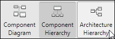
Observe the architecture hierarchy view that corresponds to the same set of components.
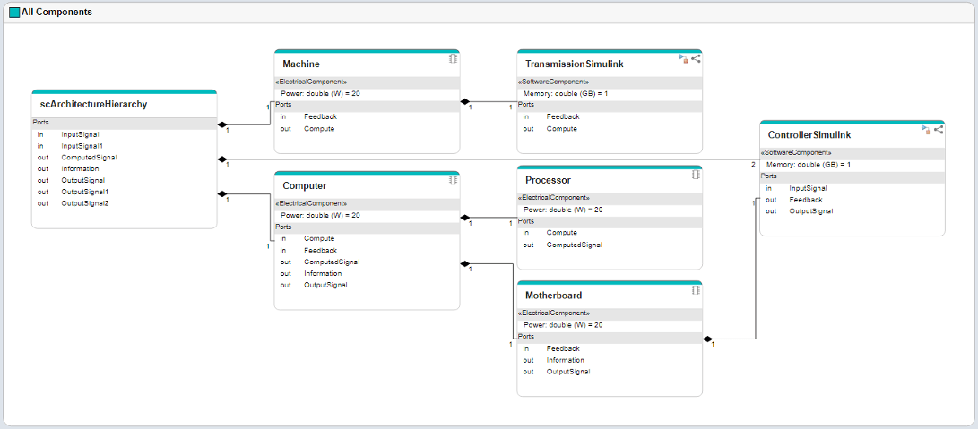
The architecture hierarchy diagram starts with the root architecture. The root corresponds to the boundary of the system. A box in an architecture hierarchy diagram represents a referenced model and appears only once even if it is referenced multiple times in the same model. For example,
ControllerSimulink, a referenced model that appears on three components, has connections showing the multiplicity. The lines show the relationship betweenContollerSimulinkand its parents.
See Also
Tools
- Architecture Views Gallery | Interface Editor | Requirements Editor (Requirements Toolbox) | Requirements Manager (Requirements Toolbox)
Functions
openViews|createView|getView|deleteView|modifyQuery|setPortQuery|runQuery|removeQuery|addElement|removeElement|getQualifiedName|createSubGroup|getSubGroup|deleteSubGroup|getQualifiedName|lookup
Objects
systemcomposer.view.View|systemcomposer.view.ElementGroup|systemcomposer.query.Constraint|systemcomposer.interface.DataInterface|systemcomposer.interface.DataElement