Author Architecture Models Through Component Diagram Views
You can edit your System Composer™ model from the component diagram canvas in the Architecture Views Gallery.
Create a new component diagram view.
Interactively add, edit, and delete components, ports, and connections.
Apply stereotypes and create custom queries for your views.
Pivot to the composition to modify Simulink® behaviors.
For a roadmap of the views topics, see Create Custom Views Using Architecture Views Gallery.
Create Component Diagram and Architecture Model
A system in System Composer for a real application is usually large and complex. The system typically consists of many complex functions working together to fulfill the system requirements. As you design and analyze such architectures, you must understand existing components and recognize what needs to be added. A component diagram represents a view with components, ports, and connectors based on how the model is structured.
Create Component Diagram View
Create or open your System Composer architecture model. To create a new view:
To open the Architecture Views Gallery, navigate to Modeling > Architecture Views.
To create a new view, select New > View.
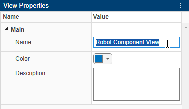
In View Properties on the right pane, in the Name text box, enter a name for this view, for example,
Robot Component View. If necessary, choose a color and enter a description.
Create and Add Components
Design a mobile robotic arm where a sensor senses position and trajectory planning
computes a path to a location that the robot needs to reach using motion. The
architecture model for this system could consist of three primary components:
Sensors, Trajectory Planning, and
Motion. You can represent these components in System Composer
using three Component blocks.
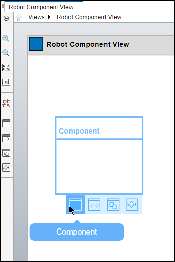
To create a component, use one of these two methods.
In the canvas, left-click and drag the pointer to create a rectangle. To see the component outline, release the pointer. To commit, select Component.
Click and drag a Component block from the left-side palette.
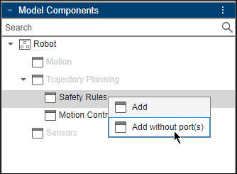
To add existing components to the view, drag components from Model Components. To remove components from the view, select a component. On the Architecture Views Gallery toolstrip, in the Components section, click Remove.
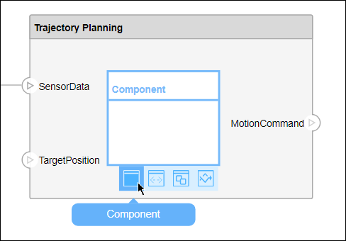
Authoring architecture models from a component diagram view allows you to edit multiple hierarchies at the same time. Press the Ctrl key, left-click, and drag the pointer inside of a component to create a new child component. You can also add ports and connections to child components from the top-level view.
Add Ports and Connections
Represent the relationship between components by defining interface ports. You can organize the diagram by positioning ports in any position on any edge of the component.
Pause over the side of a component. A plus (+) sign and a port outline appear.
Click the port outline. A set of options appear for an
Input,Output, orPhysicalport.To commit the port, select Output. You can also name the port.
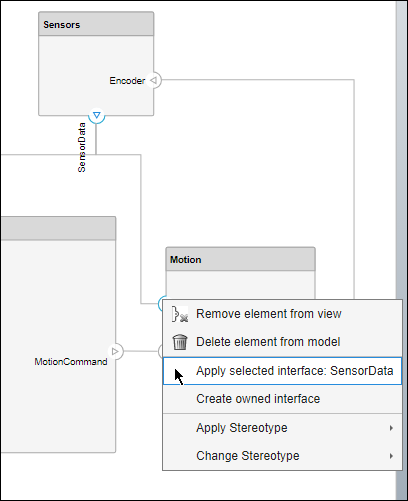
A connector allows two components to interact without defining the nature of the interaction. Set an interface on a port to define how the components interact.
Connections are visual representations of data flow from an output port to an input port. For example, a connection from a motor to a sensor carries positional information.
Connect two ports by dragging a line:
Click one of the ports.
Keep the pointer pressed while dragging a line to the other port.
Release the pointer at the destination port. A black line indicates the connection is complete. A red-dotted line appears if the connection is incomplete.

For more information on composition editing, see Compose Architectures Visually.
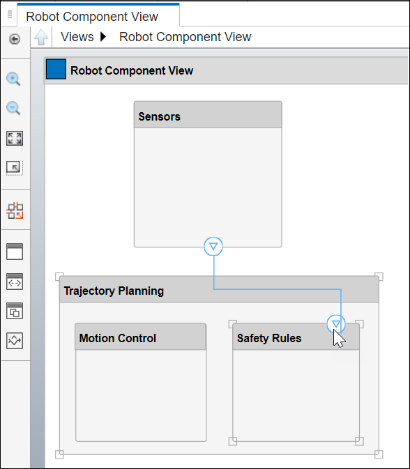
In architectural views, you can also utilize connectors to connect components across different hierarchies.
Define Interfaces
Use the Interface Editor in the Architecture Views Gallery to manage interfaces, assign interfaces to ports, add and modify data elements, and delete interfaces. The parent architecture model reflects these changes.
To open the Interface Editor tool from the Architecture Views Gallery toolstrip, in the Design section, click Interface Editor.
For more information, see Create Interfaces and Use Interface Editor in Views.
Import Profiles and Apply Stereotypes
Use profiles to add properties to components, ports, and connectors in a System Composer model. The Profile Editor is independent from a model, you must explicitly import a new profile into a model. Open the Profile Editor by navigating to Modeling > Profile Editor. You can import a profile into any open dictionaries or models.
Open the Property Inspector by navigating to Modeling > Property Inspector. Select a model element, and then select the stereotype from the Stereotype list. Alternatively, right-click a model element, select Apply Stereotype, and select a stereotype to apply to the element.
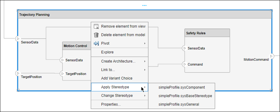
When you apply a stereotype to an element, a new set of properties appears in the Property Inspector under the name of the stereotype. To edit the properties, expand the set. You can use profiles, stereotypes, and properties later in the design process to query and analyze the system design.
For more information about profiles, stereotypes, and properties, see Apply Stereotypes to Extend Model Elements.
Create Behavior
Use Simulink model references to describe the implementation of System Composer components.
To create Simulink behavior:
Right-click a component and select
Create Simulink Behavior.From the Type list, select
Model
                            Reference
. Enter the model nameMotionSimulink. The default name is the name of the component.Click OK. A new Simulink model file named
MotionSimulinkis created in the current folder.
For more information, see Implement Component Behavior Using Simulink.
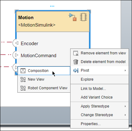
Pivot from Views to Composition
To change from views editing to model editing, right-click a component in a view and select Pivot > Composition to pivot from the component in your view to the corresponding component in your architecture model.
Modify Existing Views
Use queries to define custom viewpoints on the architecture model. View filters rely on the constraints defined by queries. Group ports in component diagram views to simplify complex networks of ports and connections.
For more information on component and port filters, see Create Architecture Views Interactively.
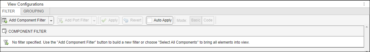
Filter Ports
To filter ports on a component in a view in the Architecture Views Gallery, click and highlight your component. A blue box appears above the component. Pause on the ellipsis (…) that appears, and select Filter Ports.
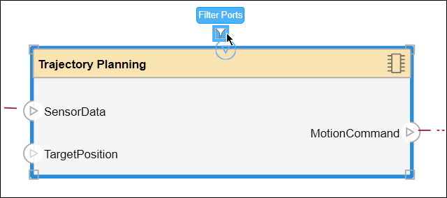
Choose which ports to show and hide on your component in the view by selecting the corresponding check boxes.

You can also interactively add components to the view without ports.
See Also
Tools
- Architecture Views Gallery | Interface Editor | Requirements Editor (Requirements Toolbox) | Requirements Manager (Requirements Toolbox)
Functions
Objects
systemcomposer.view.View|systemcomposer.query.Constraint|systemcomposer.interface.DataInterface|systemcomposer.interface.DataElement