Implement Component Behavior Using Activity Diagrams
An activity diagram describes system behavior that helps visualize the functional flow of a system through actions or decisions. Activity diagrams can help you understand how system components interact with one another. For more information, see Describe System Behavior Using Activity Diagrams.
You can add activity diagram behavior for components within System Composer™ to describe or specify flow-based behavior using nodes, pins, and flows. You can also reference an activity diagram within a Simulink® model using a Model block.
This topic uses the RobotActivity activity diagram from the
scMobileRobotExample project to show how to:
Create a System Composer component.
Create a new activity diagram behavior for a System Composer component.
Link to an existing activity diagram.
Create a new activity diagram behavior.
Simulate component with activity diagram behavior.
Create Component
To create an activity diagram behavior, you can use an existing component or create a component. To create a new component:
At the MATLAB® Command Window, enter this command.
systemcomposer
Select Architecture Model.
On the Simulation tab, select New
 , and then select
Architecture
, and then select
Architecture
 .
.Left-click and drag a component from the palette and release the mouse button to commit.
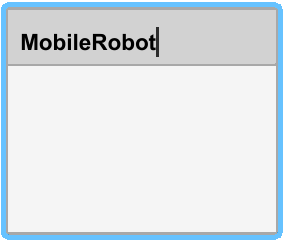
To change the name of the component, click the component, and then click its name. Change the name to
MobileRobot.
Note
You cannot create activity behavior for a component that has existing ports or subcomponents.
Create Activity Diagram Behavior
You can link a System Composer block to an existing activity diagram model. For this subsection, you can
use the RobotActivity activity diagram from the
scMobileRobotExample project. Open this project using the
following
example.
openExample('systemcomposer/OpenActivityDiagramForRobotExample');Link to an Existing Activity Diagram
To create activity diagram behavior for the RobotActivity
component, take one of these two actions: right-click menu and toolstrip.
To create activity diagram behavior for the RobotActivity
component, take one of these actions:
Right-click the component
MobileRobotand select Create Behavior > Create Activity Diagram Behavior. This action opens a new activity diagram behavior canvas.From the toolstrip, on the Modeling tab, click the down arrow in the Component section, and then select Create Activity Diagram Behavior.
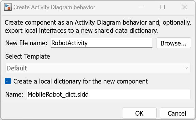
The Create Activity Diagram behavior dialog box opens. In the New
file name box, enter RobotActivity. To create a
data dictionary for the new component, select Create a local dictionary
for the new component. In the Name box,
enter the data dictionary as MobileRobot_dict.sldd.
To create the new activity diagram behavior, click OK.
Create a New Activity Diagram Behavior
You can also link to an existing activity diagram behavior model. For this
example, use the RobotActivity model.
Right-click the
MobileRobotcomponent and select Link to Model.Type or browse for the name of an activity diagram model. For this example, enter
RobotActivity.slx.To create the link, click OK.
The component displays input and output ports that correspond to the parameter nodes within the activity diagram. The input and output ports can accept data in the form of a signal or message. You can specify the mode of data that is accepted by setting the Data Mode parameter of a Parameter Node.
The icon on the top-right corner of the component represents an activity diagram behavior.

To add or remove the model preview, right-click and select Format > Content Preview.
Simulate Component with Activity Diagram Behavior
For a component with activity diagram behavior, simulation behavior depends on whether the activity diagram contains an initial node or an input parameter node.
For activity diagrams with an initial node, the simulation starts at time zero. For activity diagrams with an input parameter node, the simulation begins as soon as the input parameter node receives a token.
The simulation of an activity diagram component ends when the activity final node or the output parameter node receives a token. The time it takes for the activity final node or the output parameter node to receive a token depends on the
durationproperty of the nodes within the activity diagram.
Set Up Input Parameter Node
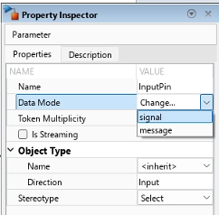
The component displays input and output ports that correspond to the parameter
nodes within the activity diagram. The input parameter node can accept data in the
form of a signal or message. To specify the type, right-click the input parameter
node. In the Property Inspector, set the Data Mode to either
message or gignal. The default value is
signal.
Use these options to set the type of communication in the system. A signal represents a continuous flow of data at each simulation time step between components.
Messages are used to model asynchronous communication and event-driven systems. For more information on modeling messages, see Simulink Messages Overview.
See Also
Functions
systemcomposer.createActivity|addNode|addParameter|getNode|getNodes|getFlow|connect|getParameter|getParameters|getPin|getPins|addPin|getParentPin|applyStereotype|removeStereotype|getStereotype|destroy|setBehaviorType
Objects
systemcomposer.activity.Action|systemcomposer.activity.Activity|systemcomposer.activity.ActivityNode|systemcomposer.activity.ActivityFinal|systemcomposer.activity.ControlNode|systemcomposer.activity.Flow|systemcomposer.activity.FlowFinal|systemcomposer.activity.Model|systemcomposer.activity.JoinFork|systemcomposer.activity.Initial|systemcomposer.activity.MergeDecision|systemcomposer.activity.Parameter|systemcomposer.activity.Pin
Tools
Blocks
- Initial Node | Action Node | Pin | Parameter Node | Decision or Merge Node | Join or Fork Node | Flow Final Node | Activity Final Node