addNode
Description
Examples
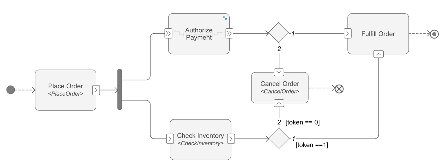
This example shows how to create an activity diagram programmatically. An activity diagram describes system behavior that models the flow of tokens from inputs to outputs through a controlled sequence of actions. You can use activity diagrams to conceptualize a system, visualize functional flow through actions or decisions, and understand how system components interact with one another. To learn more about authoring activity diagram, see, Author a Simple Activity Diagram.
In this example, you create an activity diagram to illustrate the steps involved in placing an order, checking inventory availability, and canceling the order if items are unavailable.
Create New Activity Diagram
Create a new activity diagram named AuthorActivity using the systemcomposer.createActivity function.
activityName = 'AuthorActivity';
adModel = systemcomposer.createActivity(activityName,true);
activity = adModel.Activity;
Add Initial Node and Action Nodes
Add an initial node and required action nodes using the addNode function.
init1 = addNode(activity,'init1','initial');
action1 = addNode(activity,'Place Order','action');
action2 = addNode(activity,'Authorize Payment','action');
action3 = addNode(activity,'Check Inventory','action');
action4 = addNode(activity,'Cancel Order','action');
action5 = addNode(activity,'Fulfill Order','action');
Define Action Node Behavior and Add Pins
Add the behavior type of an action node using the setBehaviorType function. You can specify the MATLAB® functions for an action node with a behavior type of MATLAB by using the BehaviorDefinition property.
setBehaviorType(action1,'MATLAB');
action1.BehaviorDefinition = 'PlaceOrder';
setBehaviorType(action2,'Activity');
setBehaviorType(action3,'MATLAB');
action3.BehaviorDefinition = 'CheckInventory';
You can add pins on an action node using the addNode function. For more information on pins, see Pin.
outPin1 = addPin(action1,'order','out');
inPin1 = addPin(action2,'order1','in');
outPin2 = addPin(action2,'order2','out');
inPin2 = addPin(action3,'order3','in');
outPin3 = addPin(action3,'order4','out');
inPin1.IsStreaming = true;
outPin2.IsStreaming = true;
Create Nested Activity
You can create a nested activity for an action node with Activity behavior type.
childActivity = action2.ChildActivity;
childAction1 = addNode(childActivity,'Enter Card Details','action');
childAction2 = addNode(childActivity,'Authenticate Details','action');
Add Control Nodes
Add a join or fork node and a merge or decision node. For more information on control nodes, see systemcomposer.activity.ControlNode.
jfork = addNode(activity,"jfork","joinfork");
decMerge1 = addNode(activity,"decMerge1","mergedecision");
decMerge2 = addNode(activity,"decMerge2","mergedecision");
Add Flow Final and Activity Final Nodes
Add a flow final node and an activity final node.
ffinal = addNode(activity,"ffinal","flowfinal");
afinal = addNode(activity,"afinal","activityfinal");
Connect Flows
Connect the flows to complete the activity diagram. You can create guard expressions for flows that output from decision node.
flow1 = connect(init1,action1);
flow2 = connect(outPin1,jfork);
flow3 = connect(jfork,inPin1);
flow4 = connect(jfork,inPin2);
flow5 = connect(outPin2,decMerge1);
flow6 = connect(outPin3,decMerge2);
flow7 = connect(decMerge2,action5);
flow8 = connect(decMerge2,action4);
flow9 = connect(decMerge1,action5);
flow10 = connect(decMerge1,action4);
flow11 = connect(action4,ffinal);
flow12 = connect(action5,afinal);
Create guard expression for flows that output from decision node.
flow7.Guard = 'token == 1';
flow8.Guard = 'token == 0';
You can use the Simulink.BlockDiagram.arrangeSystem function to improve the layout of the activity diagram model.
Simulink.BlockDiagram.arrangeSystem('AuthorActivity');Input Arguments
Output Arguments
More About
Version History
Introduced in R2026a
See Also
Functions
systemcomposer.createActivity|addParameter|getNode|getNodes|getFlow|connect|getParameter|getParameters|getPin|getPins|addPin|getParentPin|applyStereotype|removeStereotype|getStereotype|destroy|setBehaviorType
Objects
systemcomposer.activity.Action|systemcomposer.activity.Activity|systemcomposer.activity.ActivityNode|systemcomposer.activity.ActivityFinal|systemcomposer.activity.ControlNode|systemcomposer.activity.Flow|systemcomposer.activity.FlowFinal|systemcomposer.activity.Model|systemcomposer.activity.JoinFork|systemcomposer.activity.Initial|systemcomposer.activity.MergeDecision|systemcomposer.activity.Parameter|systemcomposer.activity.Pin
Tools
Blocks
- Initial Node | Action Node | Pin | Parameter Node | Decision or Merge Node | Join or Fork Node | Flow Final Node | Activity Final Node
Topics
- Describe System Behavior Using Activity Diagrams
- Establish Traceability and Extend Model Elements
- Simulate, Visualize, and Validate Activity Diagrams
- Compose Architectures Visually
- Implement Component Behavior Using Activity Diagrams
- Implement Component Behavior Using Stateflow Charts
- Implement Component Behavior Using Simscape