Variable-Frequency Second-Order Filter
이산시간 가변 주파수 2차 필터 또는 연속시간 가변 주파수 2차 필터
라이브러리:
Simscape /
Electrical /
Control /
General Control
설명
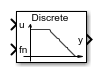
Variable-Frequency Second-Order Filter 블록은 각각 외부 주파수 입력을 갖는 4가지 유형의 2차 필터를 구현합니다. 필터는 측정 신호의 잡음을 감쇠하는 데 유용합니다.
이 블록은 다음 필터 유형을 제공합니다.
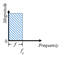
저역통과 — 차단 주파수 미만의 주파수 범위 내에 있는 신호 만 통과하도록 허용합니다.
고역통과 — 차단 주파수 를 초과하는 주파수 범위 내에 있는 신호 만 통과하도록 허용합니다.
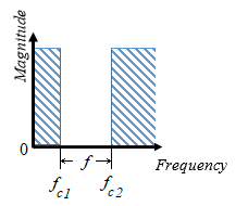
대역 통과 — 두 차단 주파수 과 사이의 주파수 범위 내에 있는 신호 만 통과하도록 허용합니다.
대역저지 — 두 차단 주파수 과 사이의 주파수 범위 내에 있는 신호 만 통과하지 못하게 합니다.
| 필터 유형 | 주파수 범위, | |
|---|---|---|
| 저역통과 |
| |
| 고역통과 |
| |
| 대역통과 |
| |
| 대역저지 |
| |


방정식
필터에 대한 2계 도함수 상태 방정식은 다음과 같습니다.
여기서 각각은 다음과 같습니다.
x는 필터 내부 상태입니다.
u는 필터 입력입니다.
ωn은 필터 고유 주파수입니다.
ζ는 필터 감쇠 인자입니다.
다음은 각 필터 유형에 대해 블록 출력 를 필터의 내부 상태의 함수로서 s 영역 전달 함수 에 매핑한 표입니다.
| 필터 유형 | 출력, | 전달 함수, |
|---|---|---|
| 저역통과 | ||
| 고역통과 | ||
| 대역통과 | ||
| 대역저지 |
초기화의 경우 다음과 같습니다.
여기서 각각은 다음과 같습니다.
은 필터의 초기 상태입니다.
은 필터에 대한 초기 입력입니다.
은 정상 상태 초기 입력의 AC 성분입니다.
은 초기 진폭입니다.
은 초기 위상입니다.
은 정상 상태 초기 입력의 DC 성분입니다.
은 초기 바이어스입니다.
s 영역에서 입니다. 따라서 초기 주파수 의 경우 다음과 같습니다.
포트
입력
출력
파라미터
참고 문헌
[1] Agarwal, A. and Lang, J. H. Foundations of Analog and Digital Electronic Circuits. New York: Elsevier, 2005.
확장 기능
버전 내역
R2018b에 개발됨