Main Content

SM PSS7C

Discrete-time or continuous-time single input PSS7C power system stabilizer

Since R2020a

  • SM PSS7C block

Libraries:
Simscape / Electrical / Control / SM Control

Description

The SM PSS7C block implements a double-input PSS7C power system stabilizer (PSS) that maintains rotor angle stability in a synchronous machine (SM) in conformance with IEEE 421.5-2016[1]. Typically, you use a PSS to enhance the damping of power system oscillations through excitation control.

You can represent two different types of dual-input power system stabilizers with this same model:

  • A stabilizer that uses electrical power and speed (or frequency) signals to calculate the integral of the accelerating power. This make the calculated stabilizer signal insensitive to mechanical changes.

  • A stabilizer that uses a combination of electrical power and either speed or frequency. To achieve the desired stabilizing signal shaping, the system uses the speed directly, without phase-lead compensation, and adds a signal that is proportional to the electrical power.

You can switch between continuous and discrete implementations of the block by using the Sample time (-1 for inherited) parameter. To configure the integrator for continuous time, set the Sample time (-1 for inherited) property to 0. To configure the integrator for discrete time, set the Sample time (-1 for inherited) property to a positive, nonzero value, or to -1 to inherit the sample time from an upstream block.

This diagram illustrates the overall structure of the PSS7C power system stabilizer:
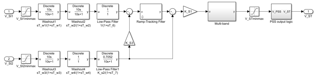
In the diagram:

  • V_SI1 and V_SI2 are the two power system stabilizer inputs. Commonly used inputs are speed, frequency, or power.

  • Two Washout (Discrete or Continuous) blocks are represented for each stabilizer input, with time constants TW1 to TW4, along with a transducer, represented by a Low-Pass Filter (Discrete or Continuous), with time constants T6 and T7.

  • To allow a ramp-tracking filter characteristic, the Ramp Tracking Filter subsystem models a network of lead-lag and low-pass filter blocks in series.

  • To provide phase compensation, the Multi-band subsystem implements a canonical state equation, with time constants Ti1 to Ti4 and gains K0 to K4.

  • The PSS output logic subsystem allows the representation of the PSS output logic associated with the generator active power output. PPSSon and PPSSoff are the threshold values used to define a hysteresis.

Ports

Input

expand all

Per-unit speed, frequency of the terminal bus voltage, compensated frequency, or electrical power, specified as a scalar.

Data Types: single | double

Per-unit electrical power, specified as a scalar.

Data Types: single | double

Output

expand all

Automatic voltage regulator input stabilization signal, as limited by VST_min and VST_max, returned as a scalar.

Data Types: single | double

Parameters

expand all

Power system stabilizer forward path gain.

Power system stabilizer transducer gain.

Power system stabilizer gain.

Transducer time constant 6, associated with the block labeled Low-Pass Filter in the diagram.

Transducer time constant 7, associated with the block labeled Low-Pass Filter1 in the diagram.

Washout time constant 1, associated with the block labeled Washout1 in the diagram.

Washout time constant 2, associated with the block labeled Washout2 in the diagram.

Washout time constant 3, associated with the block labeled Washout3 in the diagram.

Washout time constant 4, associated with the block labeled Washout4 in the diagram.

Transducer time constant 8.

Washout time constant 9.

Denominator exponent for the ramp-track filter.

Overall exponent for the ramp-track filter.

Power system stabilizer canonical gain 0 for the Multi-band subsystem.

Power system stabilizer canonical gain 1 for the Multi-band subsystem.

Power system stabilizer canonical gain 2 for the Multi-band subsystem.

Power system stabilizer canonical gain 3 for the Multi-band subsystem.

Power system stabilizer canonical gain 4 for the Multi-band subsystem.

Power system stabilizer third block gain for the Multi-band subsystem.

Power system stabilizer fourth block gain for the Multi-band subsystem.

Power system stabilizer time constant for the first block inside the Multi-band subsystem.

Power system stabilizer time constant for the second block inside the Multi-band subsystem.

Power system stabilizer time constant for the third block inside the Multi-band subsystem.

Power system stabilizer time constant for the fourth block inside the Multi-band subsystem.

Maximum power system stabilizer output to the automatic voltage regulator (AVR).

Minimum power system stabilizer output to the automatic voltage regulator (AVR).

Maximum signal value for the first stabilizer input.

Minimum signal value for the first stabilizer input.

Maximum signal value for the second stabilizer input.

Minimum signal value for the second stabilizer input.

Generator threshold for power system stabilizer activation.

Generator threshold for power system stabilizer deactivation.

Time between consecutive block executions. During execution, the block produces outputs and, if appropriate, updates its internal state. For more information, see What Is Sample Time? and Specify Sample Time.

For inherited discrete-time operation, set the sample time to -1. For discrete-time operation, set the sample time to a positive scalar. For continuous-time operation, set the sample time to 0.

References

[1] IEEE Recommended Practice for Excitation System Models for Power System Stability Studies. IEEE Std 421.5-2016. Piscataway, NJ: IEEE-SA, 2016.

Extended Capabilities

C/C++ Code Generation
Generate C and C++ code using Simulink® Coder™.

Version History

Introduced in R2020a

See Also

|