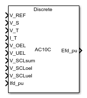
Main Content

SM AC10C

Discrete-time or continuous-time synchronous machine AC10C excitation system including an automatic voltage regulator and an exciter

Since R2023a

Libraries:
Simscape / Electrical / Control / SM Control

Description

The SM AC10C block implements a synchronous machine type AC10C excitation system model in conformance with IEEE Std 421.5-2016 [1].

Use this block to model the control and regulation of the field voltage of a synchronous machine that operates as a generator using an AC rotating exciter.

Switch between continuous and discrete implementations of the block by using the Sample time (-1 for inherited) parameter. To configure the integrator for continuous time, set the Sample time (-1 for inherited) parameter to 0. To configure the integrator for discrete time, set the Sample time (-1 for inherited) parameter to a positive scalar. To inherit the sample time from an upstream block, set the Sample time (-1 for inherited) parameter to -1.

The SM AC10C block comprises five major components:

  • The Current Compensator component modifies the measured terminal voltage as a function of the terminal current.

  • The Voltage Measurement Transducer component simulates the dynamics of a terminal voltage transducer using a low-pass filter.

  • The Excitation Control Elements component compares the voltage transducer output with a terminal voltage reference to produce a voltage error. This voltage error is then passed through a voltage regulator to produce the exciter field voltage.

  • The AC Rotating Exciter component models the AC rotating exciter, which produces a field voltage that is applied to the controlled synchronous machine. The block also feeds the exciter field current (VFE) back to the excitation system.

  • The Power Source component models the dependency of the power source for the controlled rectifier from the terminal voltage.

This diagram shows the structure of the AC10C excitation system model:
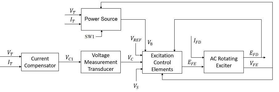
In the diagram:

  • VT and IT are the measured terminal voltage and current of the synchronous machine, respectively.

  • VC1 is the current-compensated terminal voltage.

  • VC is the filtered, current-compensated terminal voltage.

  • VREF is the reference terminal voltage.

  • VS is the power system stabilizer voltage.

  • SW1 is the power source switch that you specify for the controlled rectifier.

  • VB is the exciter field voltage.

  • EFE and VFE are the exciter field voltage and current, respectively.

  • EFD and IFD are the field voltage and current, respectively.

Current Compensator and Voltage Measurement Transducer

The block models the current compensator by using this equation:

VC1=VT+ITRC2+XC2,

where:

  • RC is the load compensation resistance.

  • XC is the load compensation reactance.

The block implements the voltage measurement transducer as a Low-Pass Filter block with the time constant TR. Refer to the documentation for the Low-Pass Filter block for information about the exact discrete and continuous implementations.

Excitation Control Elements

This diagram shows the structure of the excitation control elements:
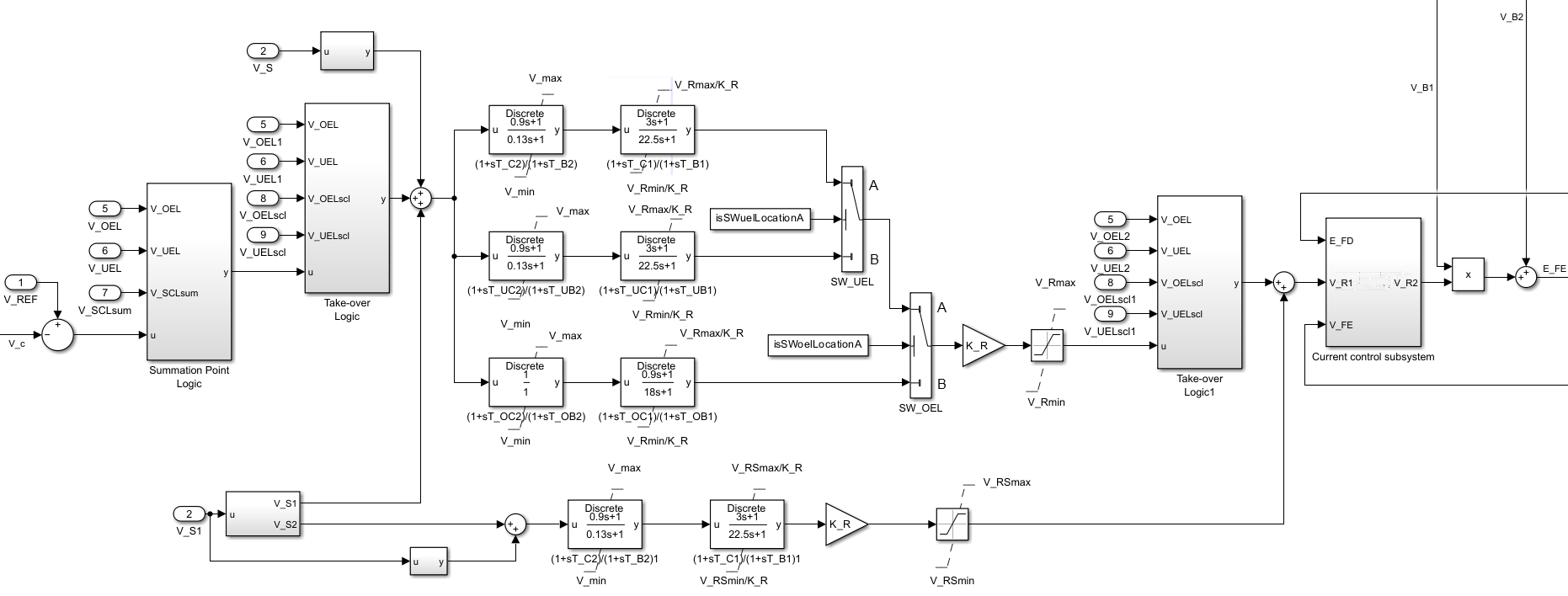
In the diagram:

  • The Summation Point Logic subsystem models the summation point input location for the overexcitation limiter (OEL), underexcitation limiter (UEL), and stator current limiter (SCL). For more information about using limiters with this block, see Field Current Limiters.

  • There are two Take-over Logic subsystems. They model the take-over point input location for the OEL, UEL and SCL voltages. For more information about using limiters with this block, see Field Current Limiters.

  • A parallel configuration of Lead-Lag (Discrete or Continuous) blocks offer independent control settings when a limiter is active. The model offers a common gain factor KR and two Lead-Lag (Discrete or Continuous) blocks for the AVR and for the underexcitation and overexcitation limiters. The SW_UEL and SW_OEL Switch blocks activate the appropriate control path when the VUEL and/or VOEL signals are connected to their respective alternate positions. The SW_UEL and SW_OEL Switch blocks are on position B when you set the Alternate UEL input locations (V_UEL) and Alternate OEL input locations (V_OEL) parameters to Take-over at voltage error.

  • The two Lead-Lag blocks in each control path model additional dynamics associated with the voltage regulator and with the underexcitation and overexcitation limiters. The first Lead-Lag block in each respective path represents a transient gain reduction, where TC2 (or TUC2 and TOC2) is the lead time constant and TB2 (or TUB2 and TOB2) is the lag time constant. The second Lead-Lag block allows the possibility of representing a transient gain increase, where TC1 (or TUC1 and TOC1) is the lead time constant and TB1 (or TUB1 and TOB1)is the lag time constant. See the documentation for the Lead-Lag block for information about the discrete and continuous implementations.

  • The control signal VR1 is either directly controlling the power stage or serves as reference for a cascaded exciter field current control loop. For more information about the Current control subsystem, see Current Control Subsystem.

Current Control Subsystem

The SM AC10C block bypasses the Current control subsystem when the SW_SS Switch block is on position “A”, when you set the Exciter field current regulator proportional gain, K_CR (pu) and Exciter field current limiter proportional gain, K_LIM (pu) parameter to 0. The Current control subsystem is active when the SW_SS Switch block is on position “B.” The Current control subsystem also offers a limiter to avoid overloads of the exciter machine and to limit the exciter current to the value of the Exciter field current limiter reference, V_FELIM (pu) parameter.

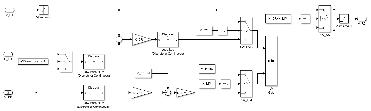
The exciter field current limiter is active when the SW_LIM Switch block is on position “B”, when the Exciter field current limiter proportional gain, K_LIM (pu) parameter is greater than zero. The limiter is bypassed when the SW_LIM Switch block is on position “A.” The SW_EXC Switch block allows you to choose the feedback variable.

Field Current Limiters

You can use different types of field current limiter to modify the output of the voltage regulator under unsafe operating conditions:

  • Use an overexcitation limiter to prevent overheating of the field winding due to excessive field current demand.

  • Use an underexcitation limiter to boost field excitation when it is too low, which risks desynchronization.

  • Use a stator current limiter to prevent overheating of the stator windings due to excessive current.

Attach the output of any of these limiters at one of these points:

  • Summation point — Use the limiter as part of the automatic voltage regulator (AVR) feedback loop.

  • Take-over point — Override the usual behavior of the AVR.

If you are using the stator current limiter at the summation point, use the input VSCLsum. If you are using the stator current limiter at the take-over point, use the overexcitation input VOELscl, and the underexcitation input VUELscl.

AC Rotating Exciter

This diagram shows the structure of the AC rotating exciter:
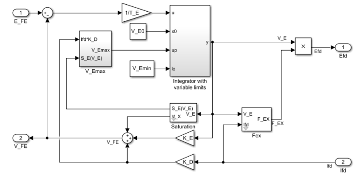
In the diagram:

  • The exciter field current VFE is the sum of three signals:

    • The nonlinear function Vx models the saturation of the exciter output voltage.

    • The proportional term KE models the linear relationship between the exciter output voltage and the exciter field current.

    • The subsystem models the demagnetizing effect of the load current on the exciter output voltage using the demagnetization constant KD in the feedback loop.

  • The Integrator with variable limits subsystem integrates the difference between EFE and VFE to generate the exciter alternator output voltage VE. TE is the time constant for this process.

  • The nonlinear function FEX models the exciter output voltage drop from the rectifier regulation. This function depends on the constant KC, which itself is a function of commutating reactance.

  • The parameters VEmin and VFEmax model the lower and upper limits of the rotating exciter.
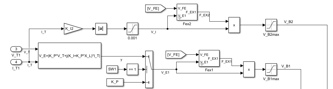
Power Source

You can use different power source representations for the controlled rectifier by setting the Power source selector SW1 parameter value. To derive the power source for the controlled rectifier from the terminal voltage, set the Power source selector SW1 parameter to Position A: power source derived from terminal voltage. To specify that the power source is independent of the terminal voltage, set the Power source selector SW1 parameter to Position B: power source independent from the terminal conditions.

Ports

Input

expand all

Voltage regulator reference set point, in per-unit representation, specified as a scalar.

Data Types: single | double

Input from the power system stabilizer, in per-unit representation, specified as a scalar.

Data Types: single | double

Terminal voltage magnitude, in per-unit representation, specified as a scalar.

Data Types: single | double

Terminal current magnitude, in per-unit representation, specified as a scalar.

Data Types: single | double

Input from the overexcitation limiter, in per-unit representation, specified as a scalar.

Dependencies

  • To ignore the input from the overexcitation limiter, set Alternate OEL input locations (V_OEL) to Unused.

  • To use the input from the overexcitation limiter at the summation point, set Alternate OEL input locations (V_OEL) to Summation point.

  • To use the input from the overexcitation limiter at the Take-over Logic subsystem, set Alternate OEL input locations (V_OEL) to Take-over at voltage error.

  • To use the input from the overexcitation limiter at the Take-over Logic1 subsystem, set Alternate OEL input locations (V_OEL) to Take-over at voltage regulator output.

Data Types: single | double

Input from the underexcitation limiter, in per-unit representation, specified as a scalar.

Dependencies

  • To ignore the input from the underexcitation limiter, set Alternate UEL input locations (V_UEL) to Unused.

  • To use the input from the underexcitation limiter at the summation point, set Alternate UEL input locations (V_UEL) to Summation point.

  • To use the input from the underexcitation limiter at the Take-over Logic subsystem, set Alternate UEL input locations (V_UEL) to Take-over at voltage error.

  • To use the input from the underexcitation limiter at the Take-over Logic1 subsystem, set Alternate UEL input locations (V_UEL) to Take-over at voltage regulator output.

Data Types: single | double

Input from the stator current limiter when using the summation point, in per-unit representation, specified as a scalar.

Dependencies

  • To ignore the input from the stator current limiter, set Alternate SCL input locations (V_SCL) to Unused.

  • To use the input from the stator current limiter at the summation point, set Alternate SCL input locations (V_SCL) to Summation point.

Data Types: single | double

Input from the stator current limiter to prevent field overexcitation when using the take-over point, in per-unit representation, specified as a scalar.

Dependencies

  • To ignore the input from the stator current limiter, set Alternate SCL input locations (V_SCL) to Unused.

  • To use the input from the stator current limiter at the Take-over Logic subsystem, set Alternate SCL input locations (V_SCL) to Take-over at voltage error.

  • To use the input from the stator current limiter at the Take-over Logic1 subsystem, set Alternate SCL input locations (V_SCL) to Take-over at voltage regulator output.

Data Types: single | double

Input from the stator current limiter to prevent field underexcitation when using the take-over point, in per-unit representation, specified as a scalar.

Dependencies

  • To ignore the input from the stator current limiter, set Alternate SCL input locations (V_SCL) to Unused.

  • To use the input from the stator current limiter at the Take-over Logic subsystem, set Alternate SCL input locations (V_SCL) to Take-over at voltage error.

  • To use the input from the stator current limiter at the Take-over Logic1 subsystem, set Alternate SCL input locations (V_SCL) to Take-over at voltage regulator output.

Data Types: single | double

Measured per-unit field current of the synchronous machine, specified as a scalar.

Data Types: single | double

Output

expand all

Per-unit field voltage to apply to the field circuit of the synchronous machine, returned as a scalar.

Data Types: single | double

Parameters

expand all

General

Initial per-unit voltage to apply to the field circuit of the synchronous machine.

Initial per-unit voltage to apply to the terminal.

Dependencies

To enable this parameter, in the Exciter section, set Power source selector SW1 to Position A: power source derived from terminal voltage.

Initial per-unit current to apply to the terminal.

Time between consecutive block executions. During execution, the block produces outputs and, if appropriate, updates its internal state. For more information, see What Is Sample Time? and Specify Sample Time.

For inherited discrete-time operation, set this parameter to -1. For discrete-time operation, set this parameter to a positive integer. For continuous-time operation, set this parameter to 0.

If this block is in a masked subsystem or a variant subsystem that supports switching between continuous operation and discrete operation, promote this parameter to ensure correct switching between the continuous and discrete implementations of the block. For more information, see Promote Block Parameters on a Mask.

Pre-Control

Resistance used in the current compensation system. Set this parameter and Reactance component of load compensation, X_C (pu) to 0 to disable current compensation.

Reactance used in the current compensation system. Set this parameter and Resistive component of load compensation, R_C (pu) to 0 to disable current compensation.

Equivalent time constant for the voltage transducer filtering.

Control

Gain of the regulator.

Equivalent lag time constant in the second Lead-Lag (Discrete or Continuous) block of the voltage regulator. Set this parameter to 0 when the additional lag dynamics are negligible.

Equivalent lead time constant in the second Lead-Lag (Discrete or Continuous) block of the voltage regulator. Set this parameter to 0 when the additional lead dynamics are negligible.

Equivalent lag time constant in the first Lead-Lag (Discrete or Continuous) block of the voltage regulator. Set this parameter to 0 when the additional lag dynamics are negligible.

Equivalent lead time constant in the first Lead-Lag (Discrete or Continuous) block of the voltage regulator. Set this parameter to 0 when the additional lead dynamics are negligible.

Equivalent lag time constant in the second Lead-Lag (Discrete or Continuous) block of the underexcitation limiter regulator. Set this parameter to 0 when the additional lag dynamics are negligible.

Equivalent lead time constant in the second Lead-Lag (Discrete or Continuous) block of the underexcitation limiter regulator. Set this parameter to 0 when the additional lead dynamics are negligible.

Equivalent lag time constant in the first Lead-Lag (Discrete or Continuous) block of the underexcitation limiter regulator. Set this parameter to 0 when the additional lag dynamics are negligible.

Equivalent lead time constant in the first Lead-Lag (Discrete or Continuous) block of the underexcitation limiter regulator. Set this parameter to 0 when the additional lead dynamics are negligible.

Equivalent lag time constant in the second Lead-Lag (Discrete or Continuous) block of the overexcitation limiter regulator. Set this parameter to 0 when the additional lag dynamics are negligible.

Equivalent lead time constant in the second Lead-Lag (Discrete or Continuous) block of the overexcitation limiter regulator. Set this parameter to 0 when the additional lead dynamics are negligible.

Equivalent lag time constant in the first Lead-Lag (Discrete or Continuous) block of the overexcitation limiter regulator. Set this parameter to 0 when the additional lag dynamics are negligible.

Equivalent lead time constant in the first Lead-Lag (Discrete or Continuous) block of the overexcitation limiter regulator. Set this parameter to 0 when the additional lead dynamics are negligible.

Maximum per-unit regulator output.

Minimum per-unit regulator output.

Maximum per-unit output of the power system stabilizer regulator.

Minimum per-unit output of the power system stabilizer regulator.

Measurement time constant of the exciter field current regulator, in seconds.

Per-unit feedback gain of the exciter field current regulator.

Proportional per-unit gain of the exciter field current regulator.

Option to choose the feedback variable in the exciter field current regulator circuit.

Equivalent lead time constant in the exciter field current regulator. Set this parameter to 0 when the additional lag dynamics are negligible.

Equivalent lag time constant in the exciter field current regulator. Set this parameter to 0 when the additional lag dynamics are negligible.

Per-unit feedback gain of the field current limiter of the excitation system.

Per-unit proportional gain of the field current limiter of the excitation system.

If you set this parameter to a value greater than 0, the SW_LIM Switch block is on position "A" and the exciter field current limiter is active.

If you set this parameter and the Exciter field current regulator proportional gain, K_CR (pu) parameter both to 0, the SW_SS Switch block is on position "A" and the Current control subsystem is not active.

Per-unit reference of the field current limiter of the excitation system.

Location of the power system stabilizer input.

Location of the overexcitation limiter input, specified as one of these options:

  • Summation point at voltage errorV_OEL is an input of the Summation Point Logic subsystem.

  • Take-over at voltage errorV_OEL is an input of the Take-over Logic subsystem.

  • Take-over at voltage regulator outputV_OEL is an input of the Take-over Logic 1 subsystem.

Location of the underexcitation limiter input, specified as one of these options:

  • Summation point at voltage errorV_UEL is an input of the Summation Point Logic subsystem.

  • Take-over at voltage errorV_UEL is an input of the Take-over Logic subsystem.

  • Take-over at voltage regulator outputV_UEL is an input of the Take-over Logic 1 subsystem.

Location of the stator current limiter input, specified as one of these options:

  • Summation point — Uuse the V_SCLsum input port.

  • Any of the Take-over options — Use the V_OELscl and V_UELscl input ports.

Exciter

Proportional constant for the exciter field.

Time constant for the exciter field.

Rectifier loading factor. This value is proportional to the commutating reactance.

Demagnetization factor related to the exciter alternator reactances.

Exciter output voltage for the first saturation factor.

Saturation factor for the first exciter.

Exciter output voltage for the second saturation factor.

Saturation factor for the second exciter.

Maximum per-unit field current limit reference.

Minimum per-unit exciter voltage output.

Per-unit potential circuit gain coefficient.

Dependencies

To enable this parameter, set Power source selector SW1 to Position A: power source derived from terminal voltage.

Potential circuit phase angle, in degrees.

Dependencies

To enable this parameter, set Power source selector SW1 to Position A: power source derived from terminal voltage.

Per-unit potential circuit current gain coefficient.

Dependencies

To enable this parameter, set Power source selector SW1 to Position A: power source derived from terminal voltage.

Per-unit reactance associated with the potential source.

Dependencies

To enable this parameter, set Power source selector SW1 to Position A: power source derived from terminal voltage.

Per-unit loading factor of the rectifier. This value is proportional to the commutating reactance.

Position of the power source selector SW1.

Maximum per-unit available field voltage for the exciter.

Per-unit loading factor of the rectifier. This value is proportional to the commutating reactance, derived from the generator terminal current through a separate series diode bridge.

Per-unit additive circuit current gain coefficient derived from the generator terminal current through a separate series diode bridge. Set this parameter to 0 to disable the separate additive power source completely.

Maximum per-unit available field voltage for the exciter, derived from the generator terminal current through a separate series diode bridge.

References

[1] IEEE Std 421.5-2016 (Revision of IEEE Std 421.5-2005). "IEEE Recommended Practice for Excitation System Models for Power System Stability Studies." Piscataway, NJ: IEEE, 2016.

Extended Capabilities

C/C++ Code Generation
Generate C and C++ code using Simulink® Coder™.

Version History

Introduced in R2023a