Resolver-to-Digital Converter
Resolver-to-digital converter
Libraries:
Simscape /
Electrical /
Control /
Observers
Description
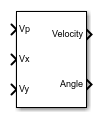
The Resolver-to-Digital Converter block models a transducer that converts the angular position or velocity of a rotating shaft to an electrical signal. Resolver-to-digital converters are commonly used in harsh, rugged environments, such as in fully electric vehicles.
The converted signal is proportional to the sine or cosine of the shaft angle.
A resolver sensor has one rotor winding with the exciter sine wave that is AC-coupled to two stator windings. The stator windings, a sine coil and a cosine coil, are mechanically positioned 90-degrees out-of-phase. As the rotor spins, the rotor position angle changes with respect to the stator windings. The resulting amplitude-modulated signals must then be gained, demodulated and post processed to extract angle and velocity information ([1] and [2]).
Equations
The block uses a phase-locked loop (PLL) to extract the angle and the velocity of the rotating shaft. The error voltage used by the PI controller is obtained as:
where:
Vpis the excitation voltage.Vxis thexvoltage for the secondary winding of the resolver.Vyis theyvoltage for the secondary winding of the resolver.Nis the number of pole pairs for the resolver.θis the angle.
Therefore, the velocity is obtained as:
and the angle is computed from the velocity using:
Examples
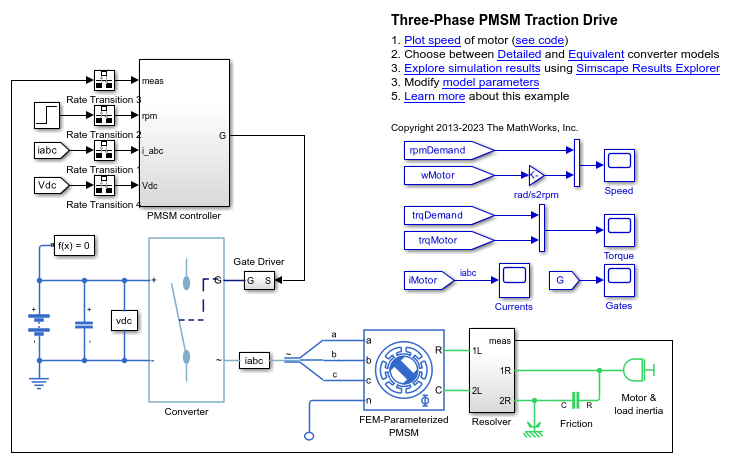
Three-Phase PMSM Traction Drive
Control the rotor speed in a permanent magnet synchronous machine (PMSM) based electrical-traction drive. A high-voltage battery feeds the FEM-Parameterized PMSM block through a controlled three-phase converter. A Rotational Friction block provides the load. The position and speed information are obtained by using a high-fidelity resolver. The PMSM controller subsystem includes a cascade control structure which has an outer speed-control loop and two inner current-control loops. During the 0.25 seconds simulation, the rotor speed demand is ramped-up from 0 to 1000 rpm.
Ports
Input
Output
Parameters
References
[1] Santanu Sarma, V.K. Agrawal, Subramanya Udupa. Software-Based Resolver-to-Digital Conversion Using a DSP. IEEE Transactions on Industrial Electronics, 55, 371-379. February 2008. (https://www.researchgate.net/publication/3219673_Software-Based_Resolver-to-Digital_Conversion_Using_a_DSP)
[2] Ankur Verma, Anand Chellamuthu. Design considerations for resolver-to-digital converters in electric vehicles. Texas Instruments, Analog Applications Journal. 2016.
Extended Capabilities
Version History
Introduced in R2019b