PMSM (Single-Phase)
Single-phase permanent magnet synchronous motor
Libraries:
Simscape /
Electrical /
Electromechanical /
Permanent Magnet
Description
The PMSM (Single-Phase) represents a single-phase permanent magnet synchronous motor (PMSM), a type of DC motor that is useful for automation applications.
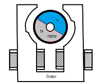
The figure shows the topology of the single-phase PMSM drive.

The figure shows the motor construction with a single pole-pair on the rotor. Single-phase PMSMs are not self-starting unless the air gap is asymmetrical.

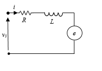
The figure shows the equivalent circuit for the PMSM (Single-Phase) block.

Equations
The motor voltage equations are
and
where:
vs is the supply voltage.
i is the instantaneous motor current.
R is the resistance of the windings.
L is the self-inductance of the windings.
e is the back-electromotive force (BEMF).
ɷs is the angular frequency of the supply voltage.
ε is the angle of the supply voltage.
The back electro-motive force (BEMF) is
where:
ɷe is the rotor electrical angular velocity.
θe is the rotor electrical angle.
ke is the BEMF constant.
Due to the large low-permeability gaps between the stator and rotor, the saturation can be neglected. Therefore, the electric torque equations are
and
where:
Te is the electric torque.
ψm is the permanent magnet flux linkage.
p is the number of pole pairs.
The mechanical equation is
where:
Jm is the rotor inertia.
TL is the torque load.
Bm is the friction coefficient.
ɷr is the rotor mechanical angular velocity.
Model Thermal Effects
You can expose thermal ports to simulate the effects of generated heat and motor temperature. To expose the thermal ports and the Thermal parameters, set the Modeling option parameter to either:
No thermal port— The block does not contain thermal ports.Show thermal port— The block contains thermal conserving ports for the stator and the rotor.
For more information about using thermal ports in actuator blocks, see Simulating Thermal Effects in Rotational and Translational Actuators.
Variables
To set the priority and initial target values for the block variables before simulation, use the Initial Targets section in the block dialog box or Property Inspector. For more information, see Set Priority and Initial Target for Block Variables.
Nominal values provide a way to specify the expected magnitude of a variable in a model. Using system scaling based on nominal values increases the simulation robustness. You can specify nominal values using different sources, including the Nominal Values section in the block dialog box or Property Inspector. For more information, see System Scaling by Nominal Values.
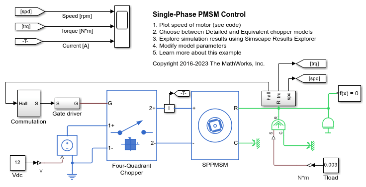
Examples
Limitations and Assumptions
The machine air gap is free of saliency effects.
The stator current has negligible effect on the flux distribution under normal operating conditions.
The hysteresis, saturation effects, and eddy currents are neglected.
Ports
Conserving
Parameters
References
[1] Ertugrul, N. and C. Doudle. “Dynamic analysis of a single-phase line-starting permanent magnet synchronous motor.” Proceedings of International Conference on Power Electronics, Drives and Energy Systems for Industrial Growth. Vol. 1, 1996, pp. 603–609.
Extended Capabilities
Version History
Introduced in R2018b

