Selective Model Visualization
What Is Visualization Filtering?
A multibody model can get so complex that you cannot easily tell its components apart. Solids, bodies, and multibody subsystems often hide behind each other, hindering your efforts to examine geometry, pose, and motion on model update or during simulation.
Visualization filtering is a Multibody Explorer feature that lets you selectively show and hide parts of your model. By showing only those parts that you want to see, you can more easily discern any components placed within or behind other components—such as an engine piston traveling inside a cylinder casing.
The figure shows an example of visualization filtering. Two cylinders, one at the front and one at the rear, are hidden in the model visualization of the TranslationalInterfaceExample featured example. For a tutorial showing how to use visualization filtering, see Selectively Show and Hide Model Components.

Changing Component Visibility
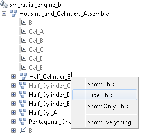
You can show and hide components through a context-sensitive menu accessible in the Model Tree pane of Multibody Explorer. Right-click a model-tree node to open the menu and select the desired option. The figure shows the visualization filtering menu.

Visualization Filtering Options
The visualization filtering menu provides four options for you to select from:
Show This— Enable visualization for the selected component. This option has no effect if the component is already visible.Hide This— Disable visualization for the selected component. This option has no effect if the component is already hidden.Show Only This— Enable visualization for the selected component and disable visualization for the remainder of the model. This option has no effect if the selected component is already the only component visible.Show Everything— Enable visualization for every component in the model. This option has no effect if every component in the model is already visible.
Components You Can Filter
You can filter the visualization of any component with solid geometry. This includes individual solids, bodies, and multibody subsystems. In general, if a subsystem contains at least one Solid block, then you can switch its visualization on and off.
Frames, joints, constraints, forces, and torques have no solid geometry to visualize and
therefore cannot be filtered in Multibody Explorer. You can still open the
visualization filtering context-sensitive menu by right-clicking these
nodes, but only one option is active—Show
Everything.
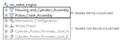
The Model Tree pane identifies any node not being visualized by graying out its name. This includes nodes that can be visualized but are currently hidden and nodes that cannot be visualized at all. The figure shows an example with the grayed-out names of nodes not being visualized.

Model Hierarchy and Tree Nodes
Multibody models are hierarchical in nature. They often contain multibody subsystems comprising body subsystems, each with one or more solids. The Model Tree pane of Multibody Explorer represents such a model structure through nodes arranged hierarchically. A node is a parent node if it contains other nodes, and a child node if it appears under another node. Nodes can simultaneously be children to some nodes and parents to others.
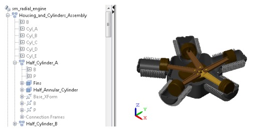
The figure shows portion of the Model Tree pane of the
TranslationalInterfaceExample featured example. The
Half_Cylinder_A node is a child to the Housing_and_Cylinder_Assembly node
and a parent to the Fins and Half_Annular_Cylinder nodes.

Filtering Hierarchical Subsystems
Any changes to the visualization settings of a tree node apply equally to all children of
that node, if any. Nodes higher up in the model tree are not affected. As
shown in the following figure, hiding the Half_Cylinder_A node in the
TranslationalInterfaceExample model causes the Fins
and Half_Annular_Cylinder nodes (children nodes) to hide, but not the
Housing_and_Cylinders_Assembly node (parent node) or the Half_Cylinder_B
node (sibling node).

If you want to show part of a subsystem you have previously hidden, you
can change the visibility settings for the children nodes that you want to
show. For example, if after hiding the Half_Cylinder_A node, you want to
show the Fins child node, you need only right-click the Fins node and select
Show This. Such changes have no effect on the
remainder of the Half_Cylinder_A parent node.
Updating Models with Hidden Nodes
The following apply when you update or simulate a model with previously hidden nodes:
If the model remains unchanged, the node visibility settings remain unchanged—that is, the hidden nodes remain hidden and the visible nodes remain visible. This happens even if you save the Multibody Explorer configuration to the model by clicking the
 icon.
icon.If you close Multibody Explorer before updating the model, Multibody Explorer reopens with all nodes visible, including any nodes you may have previously hidden.
If you change the name of a block corresponding to a hidden node—e.g., a Solid block or a Subsystem block containing a Solid block—the hidden node and any children nodes it may have become visible.
If you uncomment a block that corresponds to a hidden node and that you had previously commented out, the hidden node and any children nodes it may have become visible.
If you add to a hidden Subsystem block a Solid block or another Subsystem block with a Solid block, the child node corresponding to the new block becomes visible upon model update but the visibility of the hidden parent node remains unchanged.
If you change the parameters of a block corresponding to a hidden node, that node and its children nodes retain their original visibility settings—that is, hidden nodes remain hidden and visible nodes remain visible.
Alternative Ways to Enhance Visibility
Visualization filtering is not the only approach you can use to enhance component visibility in a model. However, it is often the simplest. It is also the only approach that doesn’t require you to modify the model in any way. Alternative approaches you can use include:
Lowering the opacity of obstructive components—those obscuring other parts of the model—for example, making the cylinder encasing an engine piston transparent.
Modeling obstructive components only in part—for example, treating engine cylinders as half-cylinders to preserve piston visibility during simulation.
Omitting obstructive components altogether if they serve a purely aesthetic purpose and have no impact on model dynamics—for example, removing the cylinder subsystems from the
TranslationalInterfaceExamplefeatured example.Commenting out or through obstructive components if they serve a purely aesthetic purpose and have no impact on model dynamics—for example, removing the cylinder subsystems from the
TranslationalInterfaceExamplefeatured example.