Constant Velocity Joint
Joint that enforces a constant-velocity kinematic constraint between two shafts

Libraries:
Simscape /
Multibody /
Joints
Description
The Constant Velocity Joint block enforces a constant-velocity (CV) kinematic constraint between its base and follower frames, whose origins are coincident throughout the simulation. Specifically, if the Z-axes of the base and follower frames are both fixed with respect to a common reference frame, the Z-components of the two frames' angular velocities with respect to the common reference frame are equal.
The block has two degrees of freedom that allow the Z-axes of the base and follower frames to be arbitrarily oriented relative to each other. The figure shows an example.
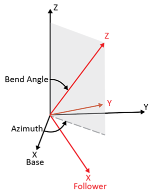
The black and red frames indicate the base and follower frames of the block. The azimuth rotation about the Z-axis of the base frame locates the plane in which the bend angle occurs. The bend angle about the resulting Y-axis, the red Y-axis, specifies the orientation of the Z-axis of the follower frame with respect to the Z-axis of the base frame.
The block has two parameterizations, Rotation Sequence (faster
simulation) or Quaternion (allows zero bend
angle), to specify the internal states of the joint. Use the
rotation-sequence parameterization whenever possible because a simulation with this
parameterization is generally faster than a simulation with the quaternion
parameterization. See Internal State for more information.
You can specify the desired initial states of the joint with the parameters under State Targets, such as the position and velocity of the azimuth and bend angle.
The block has a variety of sensing abilities. You can sense the azimuth, bend angle, and their time derivatives throughout the simulation. Furthermore, you can sense the forces and torques that act in the joint, such as constraint forces and total torque. For more information, see Composite Force/Torque Sensing section.
Faults
Using mode faults, you can change the joint modes during a simulation without modifying the
model design. The fault injection overrides the mode setting. For example, if a joint has
the Mode parameter set to Locked and the
Fault behavior parameter set to Disengaged, the
joint becomes disengaged.
To add a mode fault to a joint block, click on the joint block, in the Simscape Block tab, and the Faults section,
click Fault > Add Fault.
Alternatively, you can click the joint block, hover over the ellipsis to open the action
bar, and click the Add a fault on the block icon ![]() . You can add multiple faults to a joint block, but the
joint block can have only one active fault during a simulation.
. You can add multiple faults to a joint block, but the
joint block can have only one active fault during a simulation.
As you add faults, in the Property Inspector, under the Fault
section, specify the behavior and the trigger type of the fault. To define the fault
behavior, click the link next to the Fault Behavior. This
joint supports Locked, Normal, or
Disengaged mode. The joint blocks support these trigger types:
Always on, Timed, Manual, and
Conditional. For more details of these trigger types, see Set Fault Triggers. To trigger a
conditional fault, you can use Simulink signals, Simscape language blocks, and MATLAB
workspace variables. To set the active fault for a block, use the Fault Table. For more
details, see Access the Fault Table and Fault Dashboard.
To enable fault simulation, in the Simscape Block tab and
the Faults section, turn on the Fault
Simulation button. The fault simulation is on when the button is green and
the status is on. The simulation logs the trigger status
data. To view the data, use the Simulation Data
Inspector. Also, you can see the fault status and a summary of the triggered
faults in the Fault Dashboard. To open the Fault Dashboard, in the Simscape Block tab, click Faults >
Fault Dashboard.
To create and modify faults, you can also use Simscape™ and Simulink® fault functions. For more details, see the function section of the Simulink Fault Controls and Simscape Faults Interface.
Examples
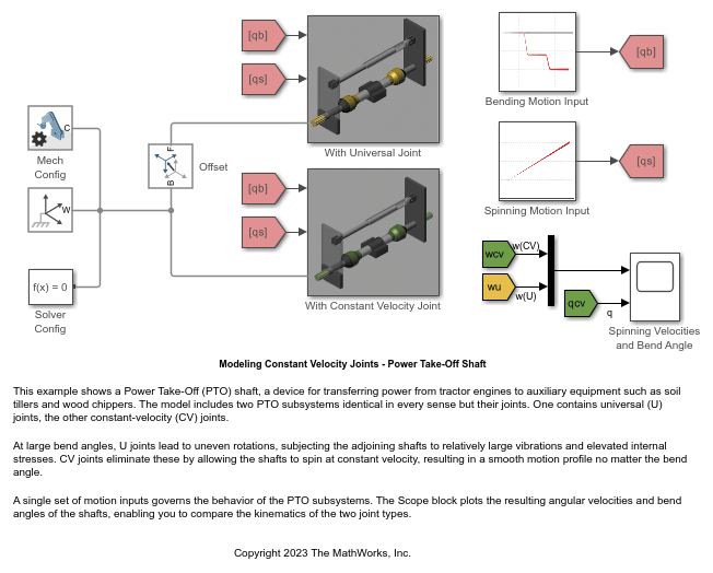
Modeling Constant Velocity Joints - Power Take-Off Shaft
A Power Take-Off (PTO) shaft, a device for transferring power from tractor engines to auxiliary equipment such as soil tillers and wood chippers. The model includes two PTO subsystems identical in every sense but their joints. One contains universal (U) joints, the other constant-velocity (CV) joints.
Ports
Frame
Input
Output
Bend angle of the CV joint, returned as a scalar. This quantity is the angle between the Z-axes of the base and follower frames of the block.
Dependencies
To enable this port, under Constant Velocity Primitive (CV) > Sensing > Bend Angle, select Position.
Velocity of the bend angle of the CV joint, returned as a scalar. This quantity equals the time derivative of the signal output from port qb.
Dependencies
To enable this port, under Constant Velocity Primitive (CV) > Sensing > Bend Angle, select Velocity.
Acceleration of the bend angle of the CV joint, returned as a scalar. This quantity equals the second time derivative of the signal output from port qb.
Dependencies
To enable this port, under Constant Velocity Primitive (CV) > Sensing > Bend Angle, select Acceleration.
Azimuth of the CV joint, returned as a scalar. This quantity is the angle of the rotation about the Z-axis of the base frame. The rotation locates the plane in which the bend angle occurs.
Dependencies
To enable this port, under Constant Velocity Primitive (CV) > Sensing > Azimuth, select Position.
Velocity of the azimuth of the CV joint, returned as a scalar. This quantity equals the time derivative of the signal output from port qa.
Dependencies
To enable this port, under Constant Velocity Primitive (CV) > Sensing > Azimuth, select Velocity.
Acceleration of the azimuth of the CV joint, returned as a scalar. This quantity equals the second time derivative of the signal output from port qa.
Dependencies
To enable this port, under Constant Velocity Primitive (CV) > Sensing > Azimuth, select Acceleration.
Composite Force/Torque Sensing
Physical signal port that outputs the constraint forces that act across the joint.
These forces maintain the translational constraints of the joint. The output has a
3-by-1 vector format and represents the force components along the
x, y, and z axes of the
resolution frame. For more information, see Force and Torque Sensing.
Dependencies
To enable this port, under Composite Force/Torque Sensing, select Constraint Force.
Physical signal port that outputs the constraint torques that act across the
joint. These torques maintain the rotational constraints of the joint. The output
has a 3-by-1 vector format and represents the torque components about the
x, y, and z axes of the
resolution frame.
Dependencies
To enable this port, under Composite Force/Torque Sensing, select Constraint Torque.
Physical signal port that outputs the total force that acts across the joint. The
total force is the sum of the of all forces transmitted between the connected frames
through the joint. The output has a 3-by-1 vector format and represents the force
components along the x, y, and
z axes of the resolution frame.
To demonstrate the total force acting on a joint, the figure shows a model using a Prismatic Joint block.

The total force includes the actuator force (FA), internal force (FI), and constraint forces (FC). For more information, see Force and Torque Sensing.
Dependencies
To enable this port, under Composite Force/Torque Sensing, select Total Force.
Physical signal port that outputs the total torque that acts across the joint. The
total torque is the sum of all torques transmitted between the connected frames
through the joint. The torque includes the actuation, internal, limit, and
constraint torques. The output has a 3-by-1 vector format and represents the torque
components about the x, y, and
z axes of the resolution frame. For more information, see
Force and Torque Sensing.
Dependencies
To enable this port, under Composite Force/Torque Sensing, select Total Torque.