주요 콘텐츠

Start-Stop Generator

R2026b

Generate start-stop signal used by signal generation, estimation, and autotuning blocks

Since R2024a

  • Start-Stop Generator block

Libraries:
Simulink Control Design / Signal Generation

Description

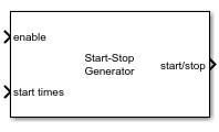
Use this block to generate a signal for the start/stop input port of signal generation, frequency response estimation, and PID autotuning blocks in Simulink® Control Design™ library. This port determines when to start and stop generating the perturbation signal in these blocks. The Start-Stop Generator block generates a signal that changes from 0 to 1 at the specified time values to enable the blocks, and from 1 to 0 to disable after the specified duration has passed.

This block is helpful when you to generate start-stop signal to enable estimation or autotuning process at different operating conditions.

Examples
Ports

Input

expand all

Specify a signal to enable (1) or disable (0) the block action.

Data Types: single | double

Specify the start times for the signals as a scalar or vector.

At the specified start times, the block generates a signal that goes from 0 to 1 for a duration specified using the Duration (sec) parameter. After the duration has passed, the signal returns to 0.

Dependencies

To enable this port, set the Source of start time points parameters to External time vector.

Data Types: single | double

Connect the output of your plant to this port. The block determines the current operating state of the system and generates the start-stop signal once the output signal is at steady state. To configure steady-state detection use the Steady-state settings parameters.

Dependencies

To enable this port, set the Source of start time points parameters to Time after reaching steady-state.

Data Types: single | double

Output

expand all

Start-stop signal. The value of the signal changes from:

  • Negative or zero to positive at the values specified using start times or at steady-state times determined using Steady-state settings.

  • Positive to negative or zero after the duration specified in Duration (sec) has passed.

Typically, you use this signal to start and stop frequency response estimation, signal generation, or autotuning processes. When the enable port is set to 0, the block does not generate a start-stop signal.

Data Types: single | double

Parameters

expand all

To edit block parameters interactively, use the Property Inspector. From the Simulink Toolstrip, on the Simulation tab, in the Prepare gallery, select Property Inspector.

Specify the sample time of the generated start-stop signal.

Programmatic Use

To set the block parameter value programmatically, use the set_param function.

Parameter: DiscreteTs
Values: "0.1" (default) | positive scalar in quotes

Specify the floating-point precision based on simulation environment or hardware requirements.

Programmatic Use

To set the block parameter value programmatically, use the set_param function.

Parameter: BlockDataType
Values: "double" (default) | "single"

Specify the source of start time points as one of the following:

  • External time vector — Use the start times output port to specify explicit values of start times.

  • Time after reaching steady-state — Use the plant output signal y and Steady-state settings to determine the times to start generating the start-stop signal.

Programmatic Use

To set the block parameter value programmatically, use the set_param function.

Parameter: StartStopTriggerMethod
Values: "External time vector" (default) | "Time after reaching steady-state"

Specify the duration of the start stop signal.

Dependencies

To enable this parameter, set the Source of start time points parameters to External time vector.

Programmatic Use

To set the block parameter value programmatically, use the set_param function.

Parameter: StartStopDuration
Values: "10" (default) | "positive scalar in quotes"

Specify the number of samples after reaching steady-state for which the block delays generating a start-stop signal.

Dependencies

To enable this parameter, set the Source of start time points parameters to Time after reaching steady-state.

Programmatic Use

To set the block parameter value programmatically, use the set_param function.

Parameter: NumStartStopDelaySamples
Values: "2" (default) | "nonnegative integer in quotes"

Specify the upper bound for the operating value used to determine settling time and steady state of the operating point.

Each value of this vector corresponds to the upper bound for the operating point value at that index.

Dependencies

To enable this parameter, set the Source of start time points parameters to Time after reaching steady-state.

Programmatic Use

To set the block parameter value programmatically, use the set_param function.

Parameter: SettlingTimeUpper
Values: "[1.1 2.1 3.1]" (default) | "vector in quotes"

Specify the lower bound for the operating value used to determine settling time and steady state of the operating point.

Each value of this vector corresponds to the lower bound for the operating point value at that index.

Dependencies

To enable this parameter, set the Source of start time points parameters to Time after reaching steady-state.

Programmatic Use

To set the block parameter value programmatically, use the set_param function.

Parameter: SettlingTimeLower
Values: "[0.9 1.9 2.9]" (default) | "vector in quotes"

Specify the time interval for which the operating condition remains in steady state.

Use a vector to specify different time intervals for different operating points.

Dependencies

To enable this parameter, set the Source of start time points parameters to Time after reaching steady-state.

Programmatic Use

To set the block parameter value programmatically, use the set_param function.

Parameter: SettlingTimeInterval
Values: "5" (default) | "scalar in quotes" | "vector in quotes"

Extended Capabilities

expand all

C/C++ Code Generation
Generate C and C++ code using Simulink® Coder™.

Version History

Introduced in R2024a