Verify Model Using Simulink Control Design and Simulink Verification Blocks
This example shows how to use a combination of Simulink® Control Design™ Simulink verification blocks to assert that the characteristics of a linear system for an aircraft satisfy one of the following conditions.
Phase margin greater than 60 degrees
Phase margin less than 60 degrees with velocity less than or equal to 90% of the cruise velocity
Open the aircraft Simulink model.
open_system('scdmultiplechecks')
The aircraft model is based on a long-haul passenger aircraft flying at cruising altitude and speed. The aircraft starts with a full fuel load and follows a pre-specified eight-hour velocity profile. The model is a simplified version of a velocity control loop, which adjusts the fuel flow rate to control the aircraft velocity.
The v <= 0.9*vCruise and Assert that: PM >= 60 or if PM < 60 then v <= 0.9*vCruise blocks are Check Static Upper Bound and Assertion blocks, respectively, from the Simulink Model Verification library. In this example, you use these blocks with the Check Gain and Phase Margins block to design complex logic for assertion.
The Check Gain and Phase Margins block is configured to linearize the loop seen by the Velocity Controller block every 30 minutes of simulated time. To view the linearization settings, open the Check Gain and Phase Margins plot and open the Linearization tab.

The Check Gain and Phase Margins block is configured to perform an assertion. The assertion fails when the phase margin of the linearized system is greater than 60 degrees. You can view the phase margin bound settings on the Bounds tab.

Since the loop seen by the controller contains the summation block with negative feedback, set the feedback sign for computing the phase margin positive feedback.
To view the computed phase margins in a tabular format during simulations, set the Plot type parameter to Tabular and click Show Plot.

Design assertion logic that causes the combination of verification blocks to fail their assertion when both of the following assertion conditions are false. In other words, the assertion passes if either condition is true
Phase margin is greater than 60 degrees
Phase margin is less than 60 degrees when the velocity is less than or equal to 90% of the cruise velocity
First, configure the Check Gain and Phase Margins block to output its assertion signal. To do so, on the Assertion tab, select Output assertion signal, and click Apply.
Next, configure the v <= 0.9*vCruise block to:
Check if the aircraft velocity exceeds the cruise velocity by 0.9 times
Add an assertion output port to the block
Not stop the simulation when the assertion fails
To do so, open the block and configure the parameters as shown in the following figure.

Finally, connect the verification blocks in the model as shown in the following figure. When both of assertion conditions are false, the input to the Assert that: PM >= 60 or if PM < 60 then v <= 0.9*vCruise block is zero. As a result, the block fails its assertion and stops the simulation.
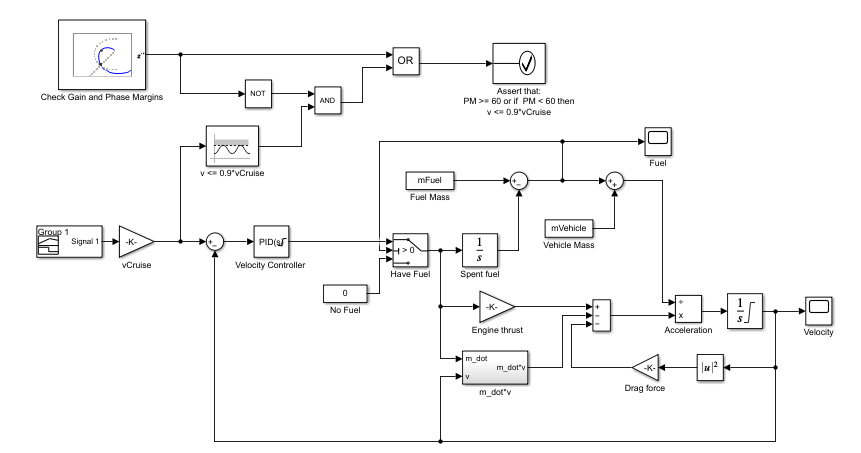
The scdmultiplechecks_final model is configured with these settings and connections.
mdl = 'scdmultiplechecks_final';
open_system(mdl)
To simulate the model, run the following code.
sim(mdl)
During the simulation, the v <= 0.9*vCruise block asserts multiple times and the Check Gain and Phase Margins block asserts twice.
You can view the phase margins that violate the bound for the Check Gain and Phase Margins block in the table.

The Assert that: PM >= 60 or if PM < 60 then v <= 0.9*vCruise does not encounter the assertion condition. Therefore, the simulation does not stop.
When a block asserts, the model generates warnings. To open the Diagnostic viewer, in the model window, click the warning link.

In the Diagnostic Viewer, you can view the details of the assertions by clicking the link.

See Also
Check Gain and Phase Margins | Check Static Upper Bound