Root Inport Mapper
Import, visualize, and map signal and bus data to root-level inports
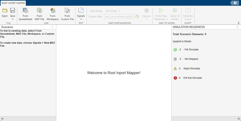
Description
The Root Inport Mapper lets you import, visualize, and map signal and bus data to root-level inports.
Before importing data, identify the signals to import and set up the data to use with root-level inport mapping. For more information, see Import Signal Data for Root Inport Mapping.
Open the Root Inport Mapper
Inport block: Open the block dialog box and click Connect Inputs.
Simulink® Editor:
Click on the Inport block in a model. In the Simulink Editor toolstrip:
Click the Root Inport tab.
Click Connect Inputs.
Simulink Editor toolstrip:
In the Prepare section of the Simulation tab, click the expander.
Click Inputs & Parameter Tuning > Connect Inputs.
Simulink Editor toolstrip:
In the Prepare section of the Simulation tab, click the expander.
Click Configuration & Simulation > Model Settings.
In the Data Import/Export pane,click the Input check box.
Click Connect Inputs.
Simulink Editor canvas:
Right-click the canvas, and then click the Model Settings button
 .
.In the Data Import/Export pane,click the Input check box.
Click Connect Inputs.
Examples
The Root Inport Mapper uses these keyboard shortcuts.
| Action | Menu Action | Keyboard Shortcut |
|---|---|---|
Open file. | Open | Ctrl+O |
Save file. | Save | Ctrl+S |
Link from spreadsheet. | From Spreadsheet | Ctrl+Shift+X |
Link from MAT-file. | From MAT-File | Ctrl+Shift+L |
Link from workspace. | From Workspace | Ctrl+Shift+B |
Create and edit new scenario in MAT-file. | Signals > New MAT-File | Ctrl+N |
Edit scenario in MAT-file. | Signals > Edit MAT-File | Ctrl+E |
Check readiness of all mapped scenario datasets. | Check Map Readiness > All Scenarios | Ctrl+Shift+A |
Check readiness of the mapped datasets of the currently selected scenarios. | Check Map Readiness > Selected Scenarios | Ctrl+Shift+S |
Check readiness of the mapped disconnected datasets. | Check Map Readiness > Unconnected Scenarios | Ctrl+Shift+U |
Check readiness of the mapped datasets that previously failed a mapping. | Check Map Readiness > Failed Scenarios | Ctrl+Shift+F |
Check readiness of the mapped datasets that previously caused warnings. | Check Map Readiness > Scenarios with Warnings | Ctrl+Shift+Y |
Apply to model. | Apply to Model | Ctrl+M |
Generate and open MATLAB® batch simulation file. | Generate Script | Ctrl+G |
Unlink all scenarios. | Unlink all scenarios | Ctrl+U |
Unlink selected scenarios. | Unlink selected scenarios | Ctrl+I |
Follow this workflow to get started using the Root Inport Mapper.
Create signal data in the MATLAB workspace.
For a Simulink model, import the data from the workspace. You can visualize the data you import.
Map the data to root-level inports.
Simulate the model.
Save the Root Inport Mapper scenario.
To specify how you want the Root Inport Mapper tool to map the signal data to a model, select from these map modes in the Map Configuration section of the toolbar.
| Goal | Map Mode |
|---|---|
Assign signals to ports according to the name of the root-inport block. If the name of a signal or bus element matches the name of a root-input port block, the data is mapped to the corresponding port. | Block Name |
Assign signals to ports according to the block path of the root-input port block. If the block path of a signal matches the block path of a root-inport block, the data is mapped to the corresponding port. | Block Path |
Assign signals to ports according to the name of the signal on the port. If the signal name of a data element matches the name of a signal at a port, the signal is mapped to the corresponding port. | Signal Name |
Assign sequential port numbers to the imported data, starting at 1. Map signals to the corresponding input ports. If there is more data than input ports, the remaining data is mapped to enable and then trigger input ports. If the data is not in the form of a dataset, it is processed in the order in which it appears in the data file. | Port Order |
Assign signals to ports according to the definitions in a custom file. To create a custom map mode, see Create and Use Custom Map Modes. | Custom |
The Root Inport Mapper tool supports the MATLAB data types or formats described in the table for imported signal data. For each data type, you can use the map modes indicated in the table.
| Data Formats | Block Name | Block Path | Signal Name | Port Order | Custom |
|---|---|---|---|---|---|
| |||||
MATLAB
| |||||
MATLAB
|
|
|
|
| |
| |||||
| |||||
Structure with time and structure without time | |||||
Data array | |||||
Array of buses | |||||
Related Examples
Parameters
File
Open an existing scenario from a previous Root Inport Mapper session. If you are working in another scenario, the Root Inport Mapper tool displays a message.

| To... | Click... |
|---|---|
Open a new scenario. Remove the existing scenario without saving it. | No |
Cancel opening a scenario. | Cancel |
To save the existing scenario, click Yes. Then click the Open button again to open an existing scenario. | Yes |
Save current Root Inport Mapper scenario to a .mldatx
file.
Link
Import Simulink data from spreadsheet.
Import Simulink data from MAT-file.
Import Simulink data from base workspace.
Import Simulink data from a custom registered file type.
Edit
Start Signal Editor to edit signals from an existing scenario MAT-file or create a new MAT-file to contain new scenarios and signals.
Map Configuration
Select map mode according to the desired action.
| Goal | Map Mode |
|---|---|
Assign signals to ports according to the name of the root-inport block. If the name of a signal or bus element matches the name of a root-input port block, the data is mapped to the corresponding port. | Block Name |
Assign signals to ports according to the block path of the root-input port block. If the block path of a signal matches the block path of a root-inport block, the data is mapped to the corresponding port. | Block Path |
Assign signals to ports according to the name of the signal on the port. If the signal name of a data element matches the name of a signal at a port, the signal is mapped to the corresponding port. | Signal Name |
Assign sequential port numbers to the imported data, starting at 1. Map signals to the corresponding input ports. If there is more data than input ports, the remaining data is mapped to enable and then trigger input ports. If the data is not in the form of a dataset, it is processed in the order in which it appears in the data file. | Port Order |
Assign signals to ports according to the definitions in a custom file. To create a custom map mode, see Create and Use Custom Map Modes. | Custom |
Specify custom map mode file. For more information on custom map mode files. see Create and Use Custom Map Modes.
Select mapping options according to the desired action.
| Goal | Option |
|---|---|
Update the model and review the data types of root-level input ports and imported data. | Update Model Automatically. Compare the signal data and input port parameters to the root-level port and display the results. If you do not select this option, the tool maps the imported data to the root-level input port but does not update the model. |
Use strong data typing when mapping data from spreadsheets. | Use Strong Data Typing with Spreadsheets. Clear
this check box to allow the Root Inport Mapper tool to automatically convert
spreadsheet input signals to the data types of the corresponding root inports.
The Root Inport Mapper tool can cast the spreadsheet data to only these data
types: |
Import bus data that is only partially defined. | Allow Partial Specification of Buses. Confirm that any partially specified bus data you import maps properly to root-level input ports. |
Identify unassigned root input ports and detect incomplete input data sets. | Notify of Missing Signals. Show inputs with missing signals. |
Map to Model
Specify subset of scenarios to map according to the desired action.
| Goal | Option |
|---|---|
Map all the scenario datasets (default). | All Scenarios ( |
Map the datasets of the scenarios currently selected in the Scenario Dataset section. | Selected Scenarios ( |
Map the disconnected datasets. | Unconnected Scenarios
( |
Map datasets that previously failed a mapping. | Failed Scenarios ( |
Map datasets that previously caused warnings. | Scenarios with Warnings
( |
Apply data to model. Clicking this button selects the Input check box in the Data Import/Export pane in the model Configuration Parameters dialog box. It also sets the Input value to the imported data variables. The status of the application displays in the Status column of the Scenarios panel.
Script
Generate a batch simulation file to run the mappings that you have set up. You can then run the script in the MATLAB Editor.
More About
You can use the Root Inport Mapper tool to import data from Excel® spreadsheets. You can also use the Root Inport Mapper tool to import signal data in CSV files on a Windows® system with Microsoft® Office installed.
The Root Inport Mapper tool does not support Excel spreadsheet charts.
Use sheet names that follow MATLAB variable name rules. If you import from a sheet whose name does not follow these rules, the Root Inport Mapper tool uses a modified sheet name. This modified sheet name follows the MATLAB variable name rules. For example, if you have a sheet name
Group
              Name
, the Root Inport Mapper uses the modified nameGroupName.Use the first row of a sheet to specify signal names. Either specify a signal name for every signal or do not specify any signal names. If you do not specify any signal names, the tool assigns signal names using the format
Signal.#For time values, use the first column of the remaining rows. The time values must increase for each row.
Put signal values in the remaining columns.
During import, the Root Inport Mapper tool converts formatted numbers from Excel spreadsheets to doubles.
The Root Inport Mapper tool does not support block path map mode for spreadsheets.
This example of a Microsoft Excel spreadsheet is set up for root-inport mapping.
The sheet name is
sigData, which is a valid MATLAB variable name.The first row contains the signal names
signal1,signal2, andsignal3.The first column has six time values that increase for each row.
In each row with a time value, columns to the right of the first column contain signal data values for each signal.

Version History
Introduced in R2012bThe Root Inport Mapper tool has added access points for context-sensitive help:
In the Scenarios pane title bar, click the context menu icon.
 .
.Right-click a row of the Scenarios pane.
