Interpreting Torque in the Angle-Based Rotational Domain
This example describes how to interpret torques in a Simscape™ angle-based rotational network. It outlines the key concepts for understanding the signs of logged torques. It examines rotational spring systems driven by torque sources at different ends, as well as a rotational system of inertias, to illustrate the torque behavior.
Governing Principles for Torque Behavior
The angle-based rotational domain uses two key principles to define torque behavior.
Principle 1: Torque Flows Through Rotational Networks
You can visualize torque flowing through the Simscape angle-based rotational network using arrows.
At any node in the network:
Torque flowing into the node is torque acting on the node from the rest of the system
Torque flowing out of the node is torque that the node applies to the rest of the system
The sign of the torque tells you whether it acts in the positive or negative rotational direction.
A quick visual rule for torque flow in a Simscape schematic is:
Arrow tail = provides torque
Arrow head = receives torque
Torque flow in the schematic mirrors torque balance in the real physical world. At every node:
Sum of torque flowing in = sum of torque flowing out
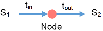
Example:

In the image:
Torque t_in flows from system S1 into the node
Torque t_out flows from the node to system S2
This means:
S1 applies torque t_in on the node
The node applies torque t_out on S2
Sign of t_in:
A positive t_in means S1 pushes the node in the positive rotational direction
A negative t_in means S1 pushes it in the negative rotational direction
About Flipping Arrows
Because every torque has an equal and opposite reaction, you can reverse the arrow directions as long as you also flip the sign. In this tutorial, arrow directions are adjusted so all shown torques are positive.
About the Positive Rotation Direction
To help you consistently think about the positive signs of angular velocity and torque, use the right‑hand rule around the axis.
Each image below shows how a positive angular velocity (ω > 0) aligns with the chosen axis direction.
The Interpreting Angle in the Angle-Based Rotational Domain example provides more information on the axis and rotational directions.
Principle 2: Align Components with the Axis Positive Direction
Two-port blocks have an internal positive direction from port B to port F.
To make the signs of Simscape torque variables intuitive:
Orient each two‑port block so its B-to-F direction matches the chosen axis positive direction.
Draw connections between components so they match the physical connections of the real components.
Block orientation on the canvas does not affect simulation results, only block connections do. However, consistent orientation makes it easier to relate simulation values to real-world behavior.
Example:

In this image:
The pink arrow shows the axis pointing to the right.
All two-port blocks are oriented with port B on the left and port F on the right, so their internal positive direction matches the axis direction.
For more details on the axis direction, see the Interpreting Angle in the Angle-Based Rotational Domain example.
Block-Specific Guidelines for Applying and Interpreting Torque
The key principles lead to the following torque concepts for different groups of blocks.
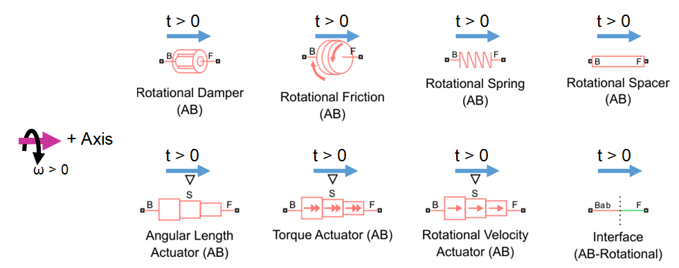
1. t > 0 in two-port element and actuator blocks means the B node drives the F node in the positive rotational direction
In two-port element and actuator blocks, the B and F ports typically represent different points in the system. These blocks all have an internal torque, t, that represents the torque acting from port B on port F. A positive internal torque indicates that port B drives port F in the positive direction, while a negative torque indicates that port B drives port F in the negative direction. Although Simscape logs only the internal torque from port B to port F, Newton's Third Law dictates that port F simultaneously exerts an equal and opposite torque on port B.
In a torque flow schematic, you can show the internal torque of a two-port block as an arrow pointing from port B to port F (when port B applies a positive torque on port F) or from port F to port B (when port B applies a negative torque on port F). This image shows torque flowing from port B to port F in the two-port element and actuator blocks.
Simscape does not determine whether t > 0 corresponds to compression or tension. The material state of the component when t > 0 depends on the component’s geometry, such as the handedness of a helical spring.
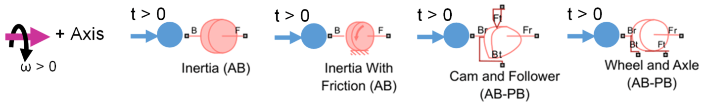
2. t > 0 in inertia and mechanism blocks means the rotational system tries to accelerate the block in the positive rotational direction
Inertia and mechanism blocks can show one or two rotational ports. When two ports are displayed, they are only for layout convenience, and the ports still represent the same physical point. Any blocks connected to port B or F are functionally connected at a single common rotational node.
These blocks log torque t using this convention:
t > 0 - torque flows into the block. The rotational system acts to drive the block in the positive rotational direction.
t < 0 - torque flows out of the block. The rotational system acts to drive the block in the negative rotational direction.
Torque flowing into the inertia accelerates it in the positive direction, . Conversely, torque flowing out of the inertia accelerates it in the negative direction. The Cam and Follower (AB-PB) and Wheel and Axle (AB-PB) mechanisms blocks exchange the absorbed/released power with the translational domain.
This image shows torque flowing into the inertia and mechanism blocks. Each blue circle represents the block absorbing torque.
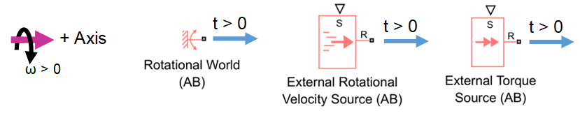
3. t > 0 in 1-port sources and the World (AB) block means the block applies torque on the system in the positive direction
The logged torque t in a source block or the Rotational World (AB) block represents the torque flowing out of the block and into the rest of the system.
t > 0 - torque flows out of the block. This torque acts to drive the attached system node in the positive direction.
t < 0 - torque flows into the block. This torque acts to drive the attached system node in the negative direction.
This image shows positive torque flowing out of the World and source blocks.
Torque in Springs Example
Open the model InterpretingTorqueSprings.
open_system('InterpretingTorqueSprings');
This model considers four different systems of a rotational spring driven by a torque source. Each system shows torque flow arrows and a physical view. In these torque flow schematics, the magnitude of the torque flow is always positive. According to Principle 2, the node at the tail of the torque flow arrow exerts torque while the node at the arrowhead receives torque.
In all systems, the positive axis direction points to the right. In the physical views, the spring endpoints, represented by red circles, each have an angle of 0 degrees when a dashed line between the axis and the endpoint points vertically upwards, aligning with the network's direction. The node attached to the wall has an angle of 0 degrees. The node connected to the torque source starts with an initial angle of 10 degrees, as specified by the spring's Relative angle parameter. The spring's relative angle is defined as , where is the angle at the spring's F node and is the angle at the spring's B node.
For more details on the axis direction, see the Interpreting Angle in the Angle-Based Rotational Domain example.
Simulate the system and plot the logged torques in the sources and springs.
open_system('InterpretingTorqueSprings');
sim('InterpretingTorqueSprings');
InterpretingTorqueSpringsPlot;
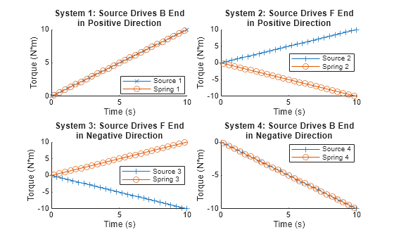
The logged torques match the block-specific torque concepts. The relative angle response of the spring depends on the location and sign of the torque source.
System 1: Positive external torque acting on the spring's B end
Physical scenario:
A positive output signal from Ramp 1 causes Torque Source 1 to apply a positive torque on the B end of Spring 1.
Consequently, the spring's B node applies a positive internal torque on the spring's F node, attempting to drive the F node in the positive direction.
Torque flow (Logged torque):
Torque flows from left to right in the schematic:
Torque flows out of Torque Source 1 (logged t > 0)
Torque flows from B to F in Spring 1 (logged t > 0)
Angles:
The Spring's B node moves in the positive direction (logged B.theta increases)
The Spring's F node is stationary (logged F.theta = 0)
The Spring's relative angle decreases (theta_rel = F.theta-B.theta decreases)
System 2: Positive external torque acting on the spring's F end
Updated physical scenario:
The locations of the Torque Source and World are swapped compared to System 1.
Now, the torque source applies a positive torque on the F end, driving the F node in the positive direction.
Now the spring B end is fixed.
Torque flow (Logged torque):
The direction of torque flow is flipped compared to System 1. Now torque flows from right to left in the schematic:
Torque still flows out of the torque source, Torque Source 2 (still logged t > 0)
Torque flows from F to B in Spring 2 (now logged t < 0)
Angles:
The Spring's F node moves in the positive direction (logged F.theta increases)
The Spring's B node is stationary (logged B.theta = 0)
The Spring's relative angle increases (theta_rel = F.theta-B.theta increases)
System 3: Negative external torque acting on the spring's F end
The spring state of System 3 is similar to System 1. Torque flows from port B to port F in the spring, and the relative angle of the spring decreases during the simulation.
System 4: Negative external torque acting on the spring's B end
The spring state of System 4 is similar to System 2. Torque flows from port F to port B in the spring, and the relative angle of the spring increases during the simulation.
Torque in Inertias Example
Open the model InterpretingTorqueInertias.
open_system('InterpretingTorqueInertias');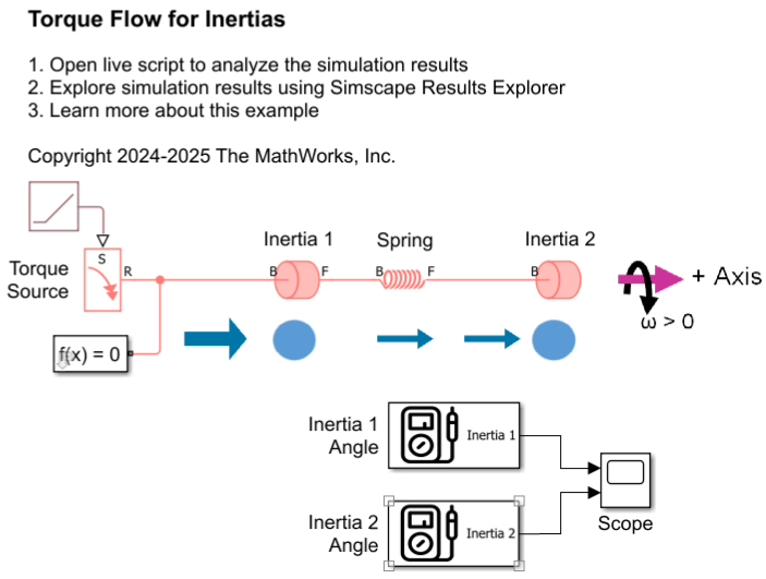
In this model, the torque source drives the Inertia 1 block, which has an inertia of 1 kg*m^2. Inertia 1 is connected to a spring. The other end of the spring is connected to the Inertia 2 block, which has a larger inertia of 10 kg*m^2. The rotational network axis points to the right. Initially, both inertias are at rest, and the spring is undeformed. The Torque source starts at 0 N*m, and ramps up at a rate of 1 N*m/s.
Simulate the system and plot the logged torques.
sim('InterpretingTorqueInertias');
InterpretingTorqueInertiasPlot;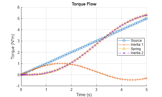
The Torque Source applies torque on Inertia 1 in the positive direction, as indicated by the torque flow arrow pointing from the Torque Source to Inertia 1 in the schematic. Inertia 1 absorbs torque when it accelerates in the positive direction (logged as positive t) and releases torque when it accelerates in the negative direction (logged as negative t). Any torque not absorbed by Inertia 1 is transferred to the Spring. Inertia 2 absorbs all the torque that flows through the spring because it is the only block connected to the F node of the Spring.
Both inertias initially have positive acceleration. The sum of torque absorbed by Inertia 1 and Inertia 2 always equals the torque provided by the Torque Source, which is consistent with balanced torque flow.