Arrays of Nodes
Arrays of nodes provide an easy way to specify element-wise connections between two or more parametric-sized arrays of components. These arrays must be of the same size but can belong to different components. For example, in battery modeling, using arrays of nodes lets you model the battery pack and the cooling plate as separate components. For more information, see Application Example.
An array of nodes (AON) is represented as a single port on the block icon. If you have two or more AON ports of the same domain type and identical size, you can establish element-wise connections between these arrays by drawing connection lines between the ports. You can also use the Array Connection blocks to connect individual elements, or subsets of elements, of AON ports of different sizes. For more information, see Graphical Connections.
Declaring Arrays of Nodes
Use a for-loop to declare an AON. The array members must all belong
to the same domain. For example, declare an array of thermal nodes:
  for i=1:N
     nodes
	H(i) = foundation.thermal.thermal;
     end
  end
You can declare the array size as an adjustable parameter of the composite component, so that the block users can modify this value.
  parameters
     N = 20; % Number of nodes
  end
Declare the parameter that specifies the array size as a unitless integer because a
for-loop iterator must be a unitless integer. For detailed information
on using arrays and for-loops, see Syntax Rules and Restrictions.
To customize the port name and location on the block icon, use the same syntax as for regular nodes, for example:
  for i=1:N
     nodes
	P(i) = foundation.electrical.electrical; % +
     end
  end
  annotations
    P : Side = top;
  end
For more information, see Customize the Names and Locations of the Block Ports.
Textual Connections
Use for-loops to specify textual element-wise connections between
arrays of components and arrays of nodes.
  for i=1:N
     connections
	connect(compX(i).H,H(i));
     end
  end
You can also index into an AON to specify textual connections between elements of the array. For example, this is how you establish a delta or polygon connection for multiphase electrical components:
component Polygon
% Delta or polygon connection
    parameters
        N = 3; % Number of phases
    end
    for i=1:N
        nodes
            p(i)=foundation.electrical.electrical;
            n(i)=foundation.electrical.electrical;
        end
    end
    connections
        connect(p(1:end-1),n(2:end));
        connect(p(end),n(1));
    end
    ...
end
For three phases, the connect(p(1:end-1),n(2:end)) syntax is
equivalent to:
        connect(p(1),n(2))
        connect(p(2),n(3))
Scalar expansion is not supported. Use a for-loop to connect a scalar
node to an AON:
component ScalarExp
    parameters
        N = 3;
    end
    components
        c = foundation.electrical.elements.resistor;
    end
    for i=1:N
        nodes
            p(i) = foundation.electrical.electrical;
            n(i) = foundation.electrical.electrical;
        end
        connections
            connect(c.p,p(i));
            % connects positive port of resistor to AON p
        end
    end
    ...
end
Similarly, use a for-loop to connect an AON to an implicit reference
node, *, because the implicit reference node is scalar:
component ImpRef
    parameters
        N = 3;
    end
    for i=1:N
        nodes
            p(i) = foundation.electrical.electrical;
        end
        connections
            connect(p(i),*);
        end
    end
    ...
end
Graphical Connections
An AON is represented as a single port on the block icon. If you have two or more AON ports of the same domain type and identical size, you can establish element-wise connections between these arrays by drawing connection lines between the ports.
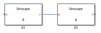
For example, component A has two arrays of electrical nodes:
component A
    parameters
        N = 5;
    end
    for i = 1:N
        nodes
            p(i) = foundation.electrical.electrical;
            n(i) = foundation.electrical.electrical;
        end
    end
    annotations
        p : Side = left;
        n : Side = right;
    end
    ...
end
If A1 and A2 are instances of component
A, the graphical connection between the two AON ports,
n and p, is equivalent to:
connect(A1.n(1), A2.p(1))
connect(A1.n(2), A2.p(2))
...
connect(A1.n(end), A2.p(end))
When using AON ports:
Like with scalar ports, error checking for the domain type is performed at edit time. You cannot connect ports of different domain types.
Error checking for the array size is performed at compile time. This means that, although you can graphically connect AON ports of different sizes, this connection generates an error when you compile the model or update the block diagram.
Implicit scalar expansion is not supported. Connecting a scalar port to an AON port also generates a compile-time error.
You can connect AON ports using Simscape Bus or Connection Port blocks with rigid interface specifications, as long as the domain types match. Similar to other graphical connections, error checking for the array size is performed at compile time. If the array sizes do not match, the connection generates a compile-time error.
You can also use the Array Connection blocks to connect individual elements, or subsets of elements, of AON ports of different sizes. Connect the AON port of the Array Connection block to the AON port of your custom block and use the element ports on the other side of the Array Connection block and the block parameters to index into the array of nodes and establish element-wise connections.
Application Example
This conceptual example shows how you can model a battery pack and a cooling plate separately, and then connect them using AON thermal ports.
The example is similar to the Case Study — Battery Pack with Fault Using Arrays example, which shows how to model a lithium-ion battery pack as a single composite component that includes component arrays of battery cells and cooling elements. The custom block based on this composite component has a scalar thermal port H.
However, in applications such as electric vehicle modeling, it is common to have a separate battery module, comprising an array of battery cells, and a separate cooling plate. For these applications, you need to model heat transfer between an array of battery cells with thermal ports and an array of convection elements by establishing element-wise connections between two arrays of thermal nodes, located in two different custom blocks.
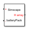
Create a battery pack component. This is a composite component that contains an array of
battery_cellcomponents, with the array size determined by theNcellsparameter.component batteryPack % Battery Pack parameters Ncells = 20; % Number of battery cells end % declare array of battery cell components for i =1:Ncells components(ExternalAccess=none) battery_cell(i) = battery_cell(cell_mass=cell_mass,... % other modifiable parameters T_init.value=T_init); end end % declare electrical nodes nodes p = foundation.electrical.electrical; % + n = foundation.electrical.electrical; % - end % declare array of thermal nodes for i=1:Ncells nodes H(i) = foundation.thermal.thermal; % H array end end annotations H : Side = right; end for i=1:Ncells connections connect(battery_cell(i).H, H(i)); end end parameters cell_mass = {1, 'kg'}; % Cell mass T_init = {293.15, 'K'}; % Initial cell temperature end % other parameters, nodes, connections, variables, equations endThe custom block generated from this component has two scalar electrical ports, + and -, on the left side and an AON thermal port, H array, on the right side of the block icon.
Create a cooling plate component. This is a composite component that contains an array of Foundation library
convectioncomponents, with the array size also determined by theNcellsparameter.component coolingPlate % Cooling Plate parameters Ncells = 20; % Number of battery cells end % declare array of convection components for i =1:Ncells components(ExternalAccess=none) convection(i) = foundation.thermal.elements.convection(area=cell_area,heat_tr_coeff=h_conv); end end % declare array of thermal nodes for i=1:Ncells nodes H(i) = foundation.thermal.thermal; % H array end end for i=1:Ncells connections connect(convection(i).H, H(i)); end end parameters cell_area = {0.1019, 'm^2'}; % Cell area h_conv = {5, 'W/(m^2 * K)'}; % Heat transfer coefficient end % other parameters, nodes, connections, variables, equations endThe custom block generated from this component has an AON thermal port H array on the left side of the block icon.

Place the two custom blocks into a model and connect their AON ports.
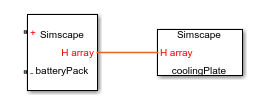
This connection line represents element-wise connections between the two arrays of thermal nodes. In other words, it connects each of the battery cells in the battery pack to the corresponding convection element in the cooling plate.
To synchronize the AON sizes in the battery pack and the cooling plate, declare a workspace variable:
number_cells = 20;
Specify the Number of battery cells parameter value in both blocks as
number_cells. This way, you can modify the number of cells by assigning a new value to thenumber_cellsvariable, with the change being reflected in the battery pack and the cooling plate simultaneously.