Main Content

Generic Engine

Generic internal combustion engine

  • Generic Engine block

Libraries:
Simscape / Driveline / Engines & Motors

Description

The Generic Engine block represents a configurable internal combustion engine that is suitable for spark-ignition and diesel applications. You can control the block using either a torque or normalized throttle physical signal. You can parameterize the block by using a third-order polynomial or by using tabulated torque or power data. Optional dynamic parameters include crankshaft inertia and response time lag. A physical signal port, FC, outputs the engine fuel consumption rate based on the fuel consumption model that you choose. Optional speed and redline controllers prevent engine stall and enable cruise control. The figure shows how the ports relate to an engine configuration.

Engine Speed, Throttle, Power, and Torque

By default, the Generic Engine block uses a programmed relationship between torque and speed that the throttle signal or the torque command signal modulates.

The block evaluates engine power demand as a function of engine speed, g(ɷ). The function provides the maximum power available for a given engine speed, ɷ. The block parameters Maximum power, Speed at maximum power, and Maximum speed normalize this function to physical maximum torque and speed values.

The normalized throttle signal, Thr, controls the engine power such that P(ɷ,Thr) = Thr·g(ɷ). When you set Model parameterization to Normalized throttle, the physical input signal Thr controls the engine power. When you choose Torque command, the block computes the normalized throttle internally. The block delivers power as a fraction of the maximum power possible in a steady state at a fixed engine speed. The figure shows the torque and power curves for the default settings.
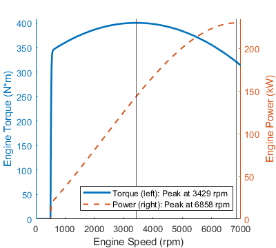
The engine torque curve is solid and blue. The engine power curve is dashed and orange.

Polynomial Engine Control

When you set Model parameterization to Normalized 3rd-order polynomial, the block uses the normalized engine speed, ɷN, to compute the speed and torque. The block defines the normalized engine speed as

ωN(ω)ωωPP

where:

  • ɷ is the current engine speed.

  • ɷPP is the engine speed at peak power.

The block treats the normalized, dimensionless engine power as a third-order polynomial such that

P(ω(ωN))=PPpN(ωN)pN(ωN)=s1ωN+s2ωN2+s3ωN3

where s1, s2, and s3 are constant polynomial coefficients and Pp is the peak power. In typical engines, the si coefficients are positive.

The block calculates engine torque at the wide-open throttle condition using the polynomial coefficients such that

T(ω(ωN))=p1+p2ωN+p3ωN2p1s1Pp/ωppp2s2Pp/ωppp3s3Pp/ωpp

The block sets the normalized engine speed at peak power such that

ωNPP=ωN(ωNPP)=1.

Substituting this equality into the formula for pN gives

s1+s2+s3=1.

This condition normalizes the power to the engine speed at peak power. The block sets the slope of pNPP) to zero, such that

s1+2s2+3s3=0.

The block defines the normalized engine speed of peak torque as

ωNPT=ωN(ωPT)=ωPTωPP<1

where the speed of peak power is greater than the speed of peak torque. The block uses the polynomial formulation to find the dimensionless, normalized torque, τN, and to sets the slope to zero such that

dτN(ωNPT)dω=s2+2s3ωNPT=0.

Solving for si using these equations yields

s1=34ωNPT2(1ωNPT)s2=ωNPTωNPT1s3=12(ωNPT1)

The block calculates the engine torque as

T(ω(ωN))=2TP3ωNPT(s1+s2ωN+s3ωN2),

where TP is the peak torque. Substituting the equation for ɷNPT yields the constraint

2TPωPP23PPωPP+PPωPT=0.

The block uses TP, PP, and ɷPT to calculate the engine speed at peak power such that

ωPP=3PP+PP(9PP8TPωPT)4TP>ωPT.

where TPɷPT is equivalent to the power at peak torque, PPT, which is always less than the peak power, PP.

Engine Power Forms for Different Engine Types

The block calculates the polynomial using the corresponding coefficients for the setting of the Engine type parameter. When you set Engine type to Spark-ignition or Diesel, the block selects the appropriate coefficients from the table. When you select Generic, the block computes these coefficients internally.

Power Demand CoefficientEngine Type
Spark-IgnitionDiesel
s1 10.6526
s2 11.6948
s 3 -1-1.3474

Fuel Consumption

The block can optionally model fuel consumption and output the results as a physical signal at port FC. To include fuel consumption in your simulation, set Fuel consumption model to one of these settings:

  • Constant per revolution

  • Fuel consumption by speed and torque

  • Brake specific fuel consumption by speed and torque

  • Brake specific fuel consumption by speed and brake mean effective pressure

You can create a visual representation of the fuel consumption. When you set Fuel consumption model to Fuel consumption by speed and torque and click the engine properties hyperlink in the block description, a live script generates a heat map plot of fuel consumption for a given torque and speed.
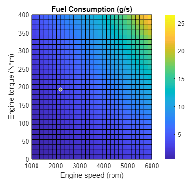
Heat map plot of fuel consumption for a given torque and speed.

This plot is in addition to the engine speed, throttle, power and torque plot. When you set Fuel consumption model to Brake specific fuel consumption by speed and torque or Brake specific fuel consumption by speed and brake mean effective pressure, the live script generates the heat map plot of fuel consumption and a separate plot for brake-specific fuel consumption.

Heat map plot of fuel consumption for a given torque and speed and heat map plot of brake-specific fuel consumption for a given torque and speed.

Idle Speed Controller Model

The idle speed controller adjusts the throttle signal to increase engine rotation below a reference speed according to:

Π=max(Πi,Πc)

and

d(Πc)dt=0.5(1tanh(4ωωrωt))Πcτ

where:

  • Π is the engine throttle.

  • Πi is the input throttle port Thr.

  • Πc is the controller throttle.

  • ω is the engine speed or crankshaft angular velocity.

  • ωr is the idle speed reference.

  • ωt is the controller speed threshold.

  • τ is the controller time constant.

The controlled throttle increases with a first-order lag from 0 to 1 when engine speed falls below the reference speed. When the engine speed rises above the reference speed, the controlled throttle decreases from one to zero. When the difference between engine velocity and reference speed is smaller than the controller speed threshold, the tanh part of the equation smooths the time derivative of the controlled throttle. The smoothing function limits the controlled throttle to the range [0,1]. The engine uses the larger of the input and controlled throttle values. If you include engine time lag, the controller changes the input before it computes the lag.

Redline Controller Model

The idle speed controller determines the minimum throttle value for maintaining engine speed, the redline controller prevents excessive speed based on a maximum throttle input. To determine the maximum throttle value, the redline controller uses the idle speed controller model equation. However, for the redline controller:

  • ωr is the redline speed reference.

  • ωt is the redline speed threshold.

  • τ is the redline time constant.

Performance

To increase simulation speed, set Fuel consumption model to No fuel consumption. When you use this setting, the block does not calculate fuel consumption regardless of port FC.

If you select any other option for Fuel consumption model, the block must perform a nonlinear computation. The block solves the equation even if the FC port, which reports the fuel consumption rate, is not connected to another block.

Predefined Parameterization

You can populate the block with pre-parameterized manufacturing data, which allows you to model a specific supplier component.

To load a predefined parameterization:

  1. In the block dialog box, next to Selected part, click the "<click to select>" hyperlink next to Selected part in the block dialogue box settings.

  2. The Block Parameterization Manager window opens. Select a part from the menu and click Apply all. You can narrow the choices using the Manufacturer drop down menu.

  3. You can close the Block Parameterization Manager menu. The block now has the parameterization that you specified.

  4. You can compare current parameter settings with a specific supplier component in the Block Parameterization Manager window by selecting a part and viewing the data in the Compare selected part with block section.

Note

Predefined block parameterizations use available data sources to supply parameter values. The block substitutes engineering judgement and simplifying assumptions for missing data. As a result, expect some deviation between simulated and actual physical behavior. To ensure accuracy, validate the simulated behavior against experimental data and refine your component models as necessary.

Assumptions and Limitations

Engines lag in their response to changing speed and throttle. The block supports lag due to a changing throttle only.

Hardware-in-the-Loop Simulation

To improve performance for HIL simulation, set the Dynamics > Time Constant parameter to No time constant - Suitable for HIL simulation.

Examples

Ports

Input

expand all

Engine torque demand as a fraction of maximum possible torque. This signal must be in the range [0,1].

Dependencies

To enable this parameter, set Input type to Normalized throttle.

Engine torque demand as a fraction of maximum possible torque, in Nm. This signal must be between 0 and the value of the Maximum torque parameter.

Dependencies

To enable this parameter, set Input type to Torque command.

Output

expand all

Power produced by the engine, in W.

Fuel consumed by the engine, in kg/s.

Conserving

expand all

Mechanical rotational conserving port associated with the engine block. This is the base port. The engine block is the physical body that contains the piston cylinders.

Mechanical rotational conserving port associated with the engine crankshaft. This is the follower port of the engine. The crankshaft transmits the power generated from the combustion process. Typically, you attach a clutch and transmission to this port.

Parameters

expand all

Engine Specifications

Whether the block receives a normalized throttle command or a torque command. The settings control the ports:

  • Normalized throttle — Enables the physical signal port Thr, which takes a unitless throttle command between zero and one.

  • Torque command — Enables the physical signal port Trq, which takes a torque command between zero and the maximum torque.

Engine model. Choose between these options based on the available data:

  • Normalized 3rd-order polynomial — Parametrize the engine with a power curve lookup table defined by power and speed characteristics.

  • Tabulated torque data — Parameterize the engine with a speed-torque table.

  • Tabulated power data — Parameterize the engine with a speed-power table.

Internal combustion process to model. You can parameterize a spark-ignited engine, a diesel engine, or a generic engine based on maximum torque, speed at maximum torque, and maximum speed.

Dependencies

To enable this parameter, set Model parameterization to Normalized 3rd-order polynomial.

Peak torque, TP, that the engine can output. This value sets the peak of the speed-torque curve.

Dependencies

To enable this parameter, set Model parameterization to Normalized 3rd-order polynomial and Engine type to Generic.

Engine speed at which the engine generates peak torque, ɷPT. This value sets the location along the torque curve where the peak occurs.

Dependencies

To enable this parameter, set Model parameterization to Normalized 3rd-order polynomial and Engine type to Generic.

Maximum power, PP, that the engine can output. This value sets the peak of the speed-power curve.

Dependencies

To enable this parameter, set Model parameterization to Normalized 3rd-order polynomial and Engine type to Spark-ignited or Diesel.

Engine speed, ɷPP, at which the engine is running at maximum power. This value sets the location along the power curve where the peak occurs.

Dependencies

To enable this parameter, set Model parameterization to Normalized 3rd-order polynomial and Engine type to Spark-ignited or Diesel.

Maximum speed, ɷmax, at which the engine can generate torque. This value sets the upper bound of the power curve.

During simulation, if ɷ exceeds this value, the simulation stops with an error. The engine maximum speed ɷmax cannot exceed the engine speed at which the engine power becomes negative.

Dependencies

To enable this parameter, set Model parameterization to Normalized 3rd-order polynomial.

Minimum speed, ɷmin, at which the engine can generate torque. This value sets the lower bound of the power curve.

During simulation, if ɷ falls below this value, the engine torque is blended to zero.

Dependencies

To enable this parameter, set Model parameterization to Normalized 3rd-order polynomial.

Threshold speed where the engine speed transitions to zero after the speed goes below ɷmin. Use this parameter to tune the simulation performance during stalls.

Dependencies

To enable this parameter, set Model parameterization to Normalized 3rd-order polynomial.

Vector of engine speeds that informs the model parameterization lookup table.

Dependencies

To enable this parameter, set Model parameterization to Tabulated torque data or Tabulated power data.

Vector of torque values for a given speed. The size of this vector must match the Speed vector parameter.

Dependencies

To enable this parameter, set Model parameterization to Tabulated torque data.

Vector of power values for a given speed. The size of this vector must match the Speed vector parameter.

Dependencies

To enable this parameter, set Model parameterization to Tabulated power data.

Method to calculate the fuel consumption at intermediate speed-torque values. Beyond the data range, fuel consumption remains constant at the final lookup table value.

Dependencies

To enable this parameter, set Model parameterization to Tabulated torque data or Tabulated power data.

Dynamics

Option to parameterize the inertia and initial velocity. You can choose to model inertia for increased fidelity or numerical stability.

Initial rotational inertia. This parameter initializes the engine inertia computation.

Dependencies

To enable this parameter, set Inertia to Specify inertia and initial velocity.

Initial angular velocity. This parameter initializes the engine inertia computation.

Option to parameterize the time constant and initial normalized engine throttle.

Time delay for the engine response. This parameter specifies the lag between the throttle signal and the engine response.

Dependencies

To enable this parameter, set Time constant to Specify time constant and initial value.

Initial normalized engine throttle. This value must be in the range [0,1]. Specify a positive value for this parameter to include lag.

Dependencies

To enable this parameter, set Time constant to Specify time constant and initial value.

Fuel Consumption

The table shows how the options for the Fuel consumption model parameter affect the availability of dependent parameters.

Fuel Consumption Parameter Dependencies

Fuel Consumption
Fuel consumption model
No fuel consumptionConstant per revolutionFuel consumption by speed and torqueBrake specific fuel consumption by speed and torqueBrake specific fuel consumption by speed and brake mean effective pressure
Fuel consumption per revolutionDisplaced volume
Revolutions per cycle
Speed vector
Torque vectorBrake mean effective pressure vector
Fuel consumption tableBrake specific fuel consumption table
Interpolation method

Fuel consumption method based on available data. The methods enable parameters that are consistent with typical industrial data. Choose from the following options:

  • No fuel consumption

  • Constant per revolution

  • Fuel consumption by speed and torque

  • Brake specific fuel consumption by speed and torque

  • Brake specific fuel consumption by speed and brake mean effective pressure

If you set Fuel consumption model to No fuel consumption, the block does not calculate fuel consumption even when the FC port to another block. Selecting this option increases simulation speed.

Constant rate of fuel consumption as a function of crankshaft revolutions. Enter the volume of fuel consumed in one crankshaft revolution.

Dependencies

To enable this parameter, set Fuel consumption to Constant per revolution.

Vector of engine torques that corresponds to the M rows of the fuel consumption lookup table.

Dependencies

To enable this parameter, set Fuel consumption to one of these settings:

  • Fuel consumption by speed and torque

  • Brake specific fuel consumption by speed and torque

  • Brake specific fuel consumption by speed and brake mean effective pressure

Vector of engine torques that corresponds to the N columns of the fuel consumption lookup table.

Dependencies

To enable this parameter, set Fuel consumption to Fuel consumption by speed and torque or Brake specific fuel consumption by speed and torque.

Matrix of fuel consumption values that correspond to the engine speed and torque vectors. The number of rows must equal the number of elements in the Speed vector parameter. The number of columns must equal the number of elements in the Torque vector parameter. The default is [.5, .9, 1.4, 1.6, 1.9, 2.7, 3.4, 4.4; 1, 1.7, 2.7, 3.1, 3.6, 5, 6, 7.4; 1.4, 2.7, 4, 4.8, 5.6, 7.5, 8.5, 10.5; 2, 3.6, 5.8, 6.7, 8, 10.4, 11.7, 13.3; 2.5, 4.8, 7.9, 9.4, 10.8, 14, 16.2, 18.6; 3.1, 6, 10.3, 11.9, 13.8, 18.4, 22, 26.5] g/s.

Dependencies

To enable this parameter, set Fuel consumption to Fuel consumption by speed and torque.

Vector of brake mean effective pressure (BMEP) values. The BMEP values satisfy the expression:

BMEP=T(2πncVd),

where:

  • T is the output torque.

  • nc is the number of cycles per revolution.

  • Vd is the cylinder displaced volume.

Dependencies

To enable this parameter, set Fuel consumption to Brake specific fuel consumption by speed and brake mean effective pressure.

When you set Fuel consumption model to Brake specific fuel consumption by speed and torque, this parameter is a matrix of brake specific fuel consumption (BSFC) rates that corresponds to engine speed and torque vectors. BSFC is the ratio of the fuel consumption rate to the output power.

When you set Fuel consumption model to Brake specific fuel consumption by speed and brake mean effective pressure, this parameter is a matrix with brake specific fuel consumption (BSFC) rates that corresponds to engine speed and brake mean effective pressure (BMEP) vectors. BSFC is the ratio of the fuel consumption rate to the output power.

For both fuel-consumption models, the number of rows must equal the number of elements in the Speed vector parameter. The number of columns must equal the number of elements in the Torque vector parameter or Brake mean effective pressure vector parameter. The default is [410, 380, 300, 280, 270, 290, 320, 380; 410, 370, 290, 270, 260, 270, 285, 320; 415, 380, 290, 275, 265, 270, 270, 300; 420, 390, 310, 290, 285, 280, 280, 285; 430, 410, 340, 320, 310, 300, 310, 320; 450, 430, 370, 340, 330, 330, 350, 380] g/(hr*kW).

Dependencies

To enable this parameter, set Fuel consumption to Brake specific fuel consumption by speed and torque or Brake specific fuel consumption by speed and brake mean effective pressure.

Piston stroke fuel displacement. This is equivalent to the area of the circular piston cylinder cross-section multiplied by the piston travel distance.

Dependencies

To enable this parameter, set Fuel consumption to Brake specific fuel consumption by speed and brake mean effective pressure.

Interpolation method to calculate fuel consumption at the intermediate speed and torque values. Fuel consumption remains constant beyond the range of the lookup table.

Dependencies

To enable this parameter, set Fuel consumption to one of these settings:

  • Fuel consumption by speed and torque

  • Brake specific fuel consumption by speed and torque

  • Brake specific fuel consumption by speed and brake mean effective pressure

Number of crankshaft revolutions in a combustion cycle. Enter 2 for a four-stroke engine or 1 for a two-stroke engine.

Dependencies

To enable this parameter, set Fuel consumption to Brake specific fuel consumption by speed and brake mean effective pressure.

Speed Control

Option to enable speed control. Speed control idles the engine at a given setpoint. Engine idle prevents stalling when the applied throttle is not enough to turn. When you enable speed control, the block asserts enough throttle to maintain at least the Idle speed reference parameter value. For more information, see Idle Speed Controller Model.

Reference angular velocity of the crankshaft. The idle speed controller maintains at least this speed.

Dependencies

To enable this parameter, select Idle speed control.

Time to respond to deviations from the value of the Idle speed reference parameter.

Dependencies

To enable this parameter, set Idle speed control to On.

Controller smoothing parameter. The Controller threshold speed smooths the controlled throttle value when the rotational speed of the engine crosses the idle speed reference. For more information, see Idle Speed Controller Model. Large values decrease controller responsiveness. Small values increase computational cost. This parameter must be positive.

Dependencies

To enable this parameter, select Idle speed control.

Option to enable the engine crankshaft maximum angular velocity limiter. When you set Redline control to On, the block works to prevent the engine speed from exceeding a maximum setpoint.

Redline control engine speed setpoint. Enter the value of the speed reference above which the redline control activates.

Dependencies

To enable this parameter, select Redline control.

Time to respond to engine speeds exceeding the value of the Redline speed parameter. Enter the value of the time constant associated with an increase or decrease of the controlled throttle.

Dependencies

To enable this parameter, select Redline control.

Angular velocity range of the redline transition. Specify the range of the region around the redline speed where the controller transitions from fully enabled to not enabled. The block uses this parameter for smoothing the controlled throttle value when the rotational speed of the engine crosses the redline speed reference. Large values decrease controller responsiveness. Small values increase computational cost.

Dependencies

To enable this parameter, select Redline control.

Extended Capabilities

C/C++ Code Generation
Generate C and C++ code using Simulink® Coder™.

Version History

Introduced in R2011a