Drive Agricultural Tractor in Vineyard Using Unreal Engine
R2026bThis example shows how to generate a trajectory for an autonomous agricultural tractor and drive it between parallel rows of vines in a vineyard using Unreal Engine® simulation. The tractor navigates at a constant velocity, covering adjacent rows in a back-and-forth pattern.
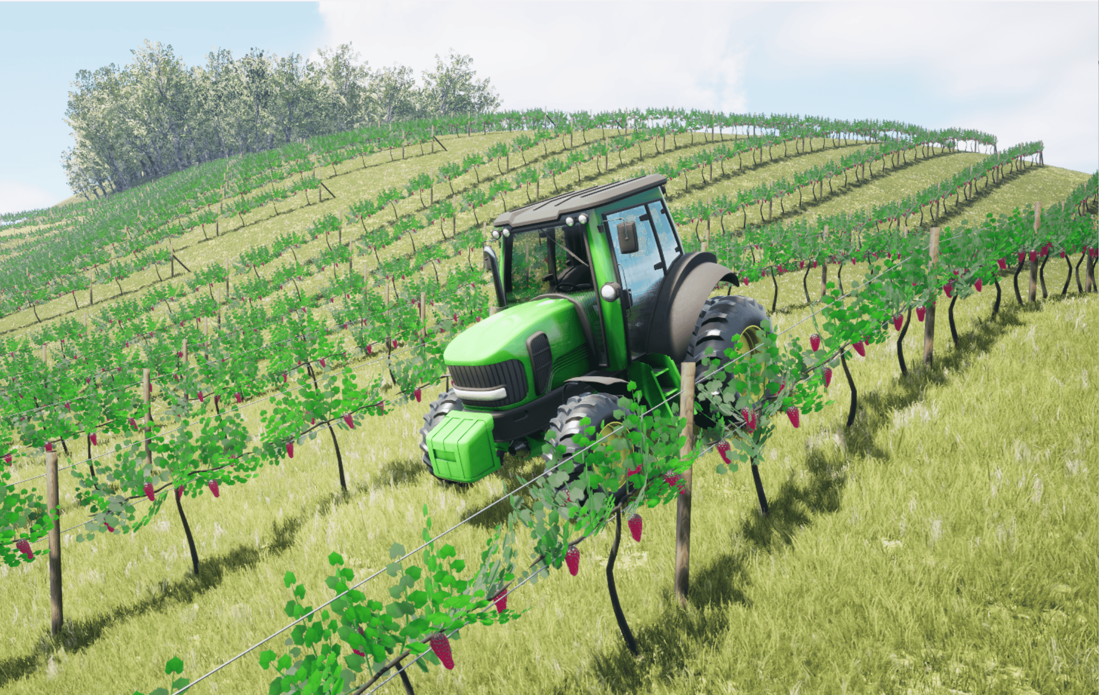
This example uses the Rolling Vineyard scene, a built-in 3D environment with multiple blocks of vine rows on rolling terrain. For more information, see the Rolling Vineyard scene.
Open Model
Open the Simulink® model.
model = 'TractorNavigationIn3DVineyard';
open_system(model);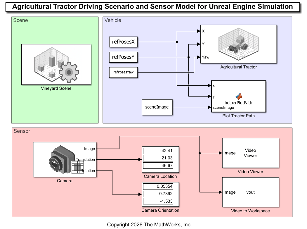
The model consists of these main components:
Scene Area — The Simulation 3D Scene Configuration (Simulink 3D Animation) block
Vineyard Sceneconfigures the Rolling Vineyard scene.Vehicle Area — The Simulation 3D Agricultural Tractor block
Agricultural Tractorplaces the tractor within the scene.Sensor Area — Captures simulation data and visualizes output:
Camera— A Simulation 3D Camera block that configures the camera mounting position and parameters.Video Viewer (Computer Vision Toolbox) block — Displays the camera output during simulation.
Video To Workspace (Computer Vision Toolbox) block — Saves camera output to the workspace.
Download Vineyard Scene
Download the Rolling Vineyard scene if not already downloaded.
if ~contains(evalc('sim3d.maps.Map.local'),'Rolling vineyard')
    sim3d.maps.Map.download('Rolling vineyard');
end
Map is successfully downloaded and is up-to-date
Verify that the list of locally installed scenes contains "Rolling vineyard".
sim3d.maps.Map.local
         MapName                                  Description                            Version
    __________________    ___________________________________________________________    _______

    "Rolling vineyard"    "A rolling hill vineyard scene with multiple rows of vines"      "1"
Configure Vineyard Scene Block
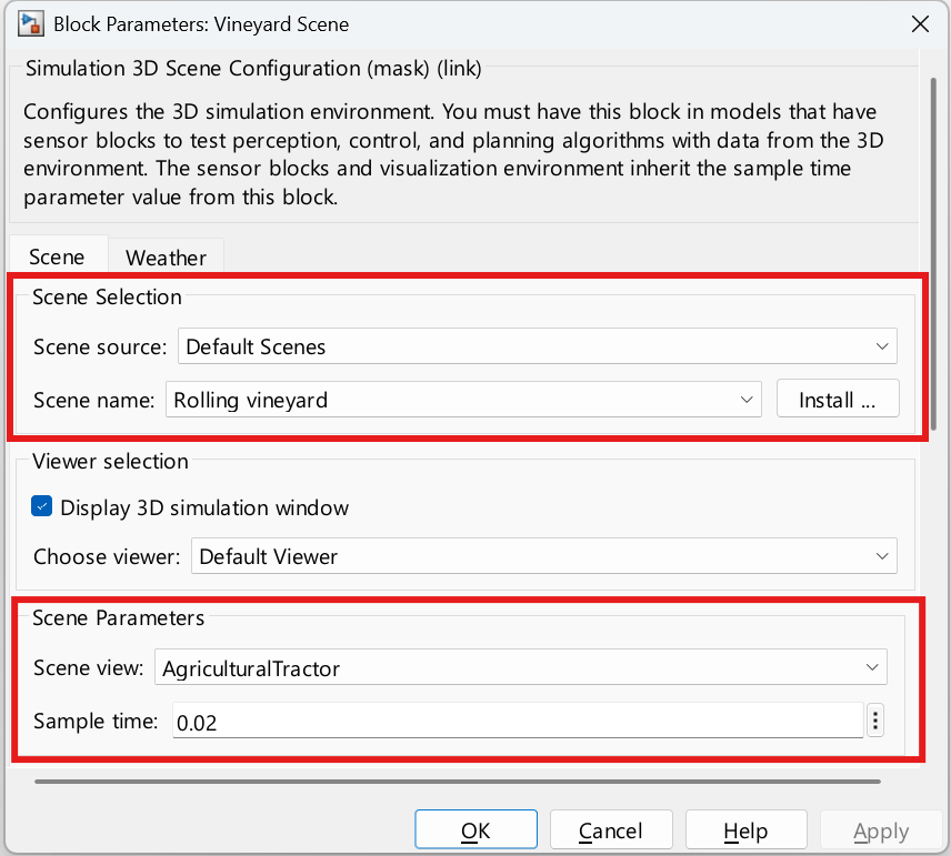
In the Simulation 3D Scene Configuration block, set the Scene parameter to "Rolling vineyard".
pathToSceneBlock = [model, '/Vineyard Scene'];
set_param(pathToSceneBlock,"SceneDesc","Rolling vineyard");
Obtain a top-down view of the vineyard scene.
showImage = false;
[sceneImage,sceneRef] = helperGetVineyardSceneImage(showImage);
The Scene view parameter controls the viewpoint of the Unreal Engine window during simulation. This parameter is set to AgriculturalTractor, which displays the scene from behind the vehicle. To view from the scene origin instead, set this parameter to root.
Define Trajectory for Tractor
The Simulation 3D Agricultural Tractor block models the vehicle in the scenario. It accepts pose inputs to control the tractor along a trajectory.
Specify a set of waypoints for the tractor to follow. Use the helperSelectSceneWaypoints helper function to interactively select waypoints in the scene.
To use a predefined trajectory, set selectWaypoints to false. To select your own waypoints, set selectWaypoints to true.
selectWaypoints =  "false";
If selectWaypoints is set to false, use the predefined trajectory.
% Set variables to predefined values if selectWaypoints is false or if the variables do not exist
if strcmp(selectWaypoints,"false") || exist("refPoses","var")==0 || exist("wayPoints","var")==0

    % Set waypoints
    waypoints = [...
        -37.2189	4.3654;
        -37.2189	20.1490;
        -37.2189	35.9327;
        -37.2189	51.7163;
        -37.2189	67.5000;
        -41.6161	67.5000;
        -41.6161	56.4716;
        -41.6161	45.4432;
        -41.6161	34.4147;
        -41.6161	23.3863;
        -41.6161	12.3579;
        -41.6161	1.3295];

    % Compute headings
    waypointsDiff = diff(waypoints);
    thetaDeg = acosd( waypointsDiff(:,1)./sqrt( waypointsDiff(:,1).^2 + waypointsDiff(:,2).^2 ) );

    % Correct for 3rd and 4th quadrants
    correctionNeeded = waypointsDiff(:,2) < 0;
    thetaDeg(correctionNeeded) = 360 - thetaDeg(correctionNeeded);

    % Set path with headings
    path = [waypoints zeros(size(waypoints,1),1,like=waypoints)];
    path(2:end,end) = thetaDeg;
    path(1,end) = thetaDeg(1);
    wayPoints = {waypoints};
    refPoses = {path};

    % Compute focus area from waypoints
    focusArea = [min(waypoints(:,1)) min(waypoints(:,2)) range(waypoints)];
end
If selectWaypoints is true, open a dialog box in which you can select waypoints interactively.
if strcmp(selectWaypoints,"true")
    % Clear any existing wayPoints and refPoses from prior runs
    clear wayPoints refPoses; %#ok<UNRCH>

    % Open interactive app to select waypoints
    hFig = helperSelectSceneWaypoints(flip(sceneImage,1),sceneRef);
    hFig.WindowState = 'maximized';
    waitfor(hFig);

    % Get area of focus
    focusArea = [min(wayPoints{1}(:,1)) min(wayPoints{1}(:,2)) max(wayPoints{1})-min(wayPoints{1})];
end
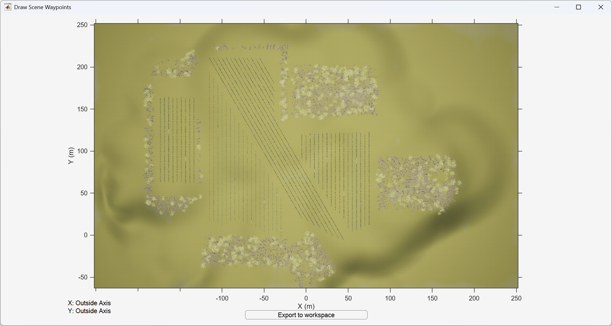
The helperSelectSceneWaypoints helper function opens a figure window displaying the selected scene.
Explore the scene by zooming and panning through the scene image. Use the mouse scroll wheel or the axes toolbar to zoom. Pause on the edge of an axis to pan in that direction.
To begin drawing a path, click the scene. A path consists of a polyline comprised of multiple points. To finish drawing the path, double-click or right-click.
After drawing a path, click Export to Workspace. In the dialog box, keep the default variable names
wayPointsandrefPoses, then click OK. Then close the figure to continue.
The dialog box exports this data to the workspace as MATLAB® variables:
wayPoints— Cell array in which each element contains an M-by-2 matrix of (x, y) waypoints in world coordinates. Each element of the cell array contains the waypoints of a different path. x and y are in meters.refPoses— Cell array in which each element contains an M-by-3 matrix of (x, y, theta). Each row of the matrix specifies the pose at the corresponding waypoint. x and y are in meters, and theta is in degrees.
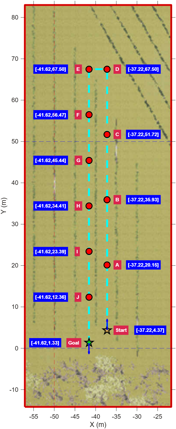
During simulation, the tractor navigates between rows of grapevines in a back-and-forth pattern. It travels to the end of a row, turns in the access lane, and proceeds to the next adjacent row. The predefined waypoints focus on a smaller area of the vineyard, as shown in this figure.
showImage = true;
helperGetVineyardSceneImage(showImage);
bufferDistance = 15.5;
focusAreaWithBuffer = focusArea + [-1 -1 2 2]*bufferDistance;
xLimitsFocusArea = [focusAreaWithBuffer(1) focusAreaWithBuffer(1)+focusAreaWithBuffer(3)];
yLimitsFocusArea = [focusAreaWithBuffer(2) focusAreaWithBuffer(2)+focusAreaWithBuffer(4)];
focusAreaBoundaryPoints = [...
    xLimitsFocusArea(1) yLimitsFocusArea(1); ...
    xLimitsFocusArea(1) yLimitsFocusArea(2); ...
    xLimitsFocusArea(2) yLimitsFocusArea(2); ...
    xLimitsFocusArea(2) yLimitsFocusArea(1); ...
    xLimitsFocusArea(1) yLimitsFocusArea(1)];
hold on
plot(focusAreaBoundaryPoints(:,1),focusAreaBoundaryPoints(:,2),"-",LineWidth=2)
hold off
This figure shows an overhead view of the focused area of the vineyard scene, with the predefined trajectory consisting of these points:
Start — The start position of the tractor.
A to J — The 10 intermediate waypoints.
Goal — The goal position of the tractor.
Smooth the waypoints into a continuous pose trajectory.
numPoses = size(refPoses{1},1);
refDirections = ones(numPoses,1); % Forward-only motion
numSmoothPoses = 20*numPoses; % Increase multiplication factor to increase the number of returned smoothed poses
[smoothRefPoses,~,cumLengths] = smoothPathSpline(refPoses{1},refDirections,numSmoothPoses);
Configure the model to stop simulation at 60 seconds. To change the tractor speed, adjust the stop time. A shorter time results in faster travel along the same path.
simStopTime = 60;
set_param(gcs,"StopTime",num2str(simStopTime));
Create a constant velocity profile for the vehicle by creating a time vector proportional to the cumulative path length.
timeVector = normalize(cumLengths,"range",[0 simStopTime]);Create the reference trajectory of poses. Specify yaw in radians.
refPosesX = [timeVector smoothRefPoses(:,1)];
refPosesY = [timeVector smoothRefPoses(:,2)];
refPosesYaw = [timeVector deg2rad(smoothRefPoses(:,3))];
Set Initial Pose of Tractor
Set the initial position and rotation of the tractor. The x- and y-position and yaw-rotation come from the first pose of the trajectory. Set the initial height of the tractor to the maximum height of the world (50 meters) so the tractor can detect and attach to the ground. Set pitch and roll to 0 to keep the vehicle horizontal.
pathToTractorBlock = [model, '/Agricultural Tractor'];
initialHeight = 50;
initialYaw = refPosesYaw(1,2);
initialPitch = 0;
initialRoll = 0;
initialRotm = eul2rotm([initialYaw initialPitch initialRoll]);
set_param(pathToTractorBlock, 'InitTractorTrans', ...
    sprintf("[%.4f, %.4f, %.4f]",refPosesX(1,2),refPosesY(1,2),initialHeight));
set_param(pathToTractorBlock,'InitTractorRot',mat2str(initialRotm,6));
Mount Sensor
The Simulation 3D Camera block models the sensor used in the scenario.
To ensure that the tractor is in view, tilt the camera downward toward the tractor by mounting the camera sensor behind the vehicle with a relative translation of [-20 0 20] meters and a relative rotation value of [0 45 0].
cameraBlockPath = [model, '/Camera'];
set_param(cameraBlockPath,'tmountOffset',"[-20 0 20]");
set_param(cameraBlockPath,'rmountOffset',"[0 45 0]");
The block outputs images captured from the simulation. During simulation, the Video Viewer block displays these images.
Simulate Model
Simulate the model. The visualization engine might take a few seconds to initialize on the first run. The AutoVrtlEnv window shows a view of the scene in the 3D environment. The Video Viewer block displays the camera output, as well as the current position and traversed path of the tractor on the map.
sim(model);
To change the view of the scene during simulation, select the Simulation 3D Scene Viewer window and follow the instructions on the Navigate in Unreal Engine Environment page.
Further Exploration
After simulating the model, try modifying the intrinsic camera parameters and observing the effects on the simulation. You can also change the type of sensor block. For example, you can substitute the Simulation 3D Camera with a Simulation 3D Fisheye Camera block or a Simulation 3D Lidar block.
You can also use a similar approach for numerous agricultural applications such as:
Autonomous Driving — Mount different sensors on the tractor to capture synthetic data for testing navigation and control algorithms before real-world deployment.
Weather Testing — Use the Simulation 3D Scene Configuration (Simulink 3D Animation) block Weather tab to adjust lighting, rain, and cloud effects, then test perception algorithms under diverse conditions.
Fleet Coordination — Use multiple Simulation 3D Agricultural Tractor blocks in your model to simulate a fleet of tractors and control each one of them independently based on your fleet coordination algorithm.

