Main Content

phased.CrossedDipoleAntennaElement

Crossed-dipole antenna element

Description

The phased.CrossedDipoleAntennaElement System object™ models a crossed-dipole antenna element which is used to generate circularly polarized fields. A crossed-dipole antenna is formed from two orthogonal short-dipole antennas. By default, one dipole lies along y-axis and the other along the z-axis in the antenna local coordinate system. You can rotate the antenna in the yz-plane using the RotationAngle property. This antenna object generates right hand or left hand circularly polarized fields, or linearly polarized fields controlled using the Polarization property. These fields are pure along the x-axis (defined by 0° azimuth and 0° elevation angles).

To compute the response of the antenna element:

  1. Create the phased.CrossedDipoleAntennaElement object and set its properties.

  2. Call the object with arguments, as if it were a function.

To learn more about how System objects work, see What Are System Objects?

Creation

Description

antenna = phased.CrossedDipoleAntennaElement creates a crossed-dipole antenna with default property values.

antenna = phased.CrossedDipoleAntennaElement(Name,Value) creates a crossed-dipole antenna with each specified property set to the specified value. You can specify additional name-value pair arguments in any order as (Name1,Value1,...,NameN,ValueN).

example

Properties

expand all

Unless otherwise indicated, properties are nontunable, which means you cannot change their values after calling the object. Objects lock when you call them, and the release function unlocks them.

If a property is tunable, you can change its value at any time.

For more information on changing property values, see System Design in MATLAB Using System Objects.

Operating frequency range of the antenna, specified as a nonnegative, real-valued, 1-by-2 row vector in the form [LowerBound HigherBound]. The antenna element has no response outside the specified frequency range. Units are in Hz.

Data Types: double

Crossed-dipole rotation angle, specified as a scalar between -45° and +45°. The rotation angle specifies the angle of rotation of the two dipoles around the x-axis. The rotation angle is measured counter-clockwise around the x-axis looking towards to origin. A default value of 0° corresponds to the case where one dipole is along the z-axis and the other dipole is along the y-axis. Units are in degrees.

Data Types: double

Polarization of the field generated by the antenna, specified as 'RHCP', 'LHCP', or 'Linear'.

  • 'RHCP' – right hand circularly polarize field. The horizontal field has a 90° phase advance compared to the vertical field.

  • 'LHCP' – left hand circularly polarize field. The horizontal field has a 90° delay compared to the vertical field.

  • 'Linear' – linearly polarized field. The horizontal and vertical fields are in phase.

Example: 'Linear'

Data Types: char | string

Usage

Description

RESP = antenna(FREQ,ANG) returns the antenna voltage response, RESP, at the operating frequencies specified in FREQ and in the directions specified in ANG.

example

Note

The object performs an initialization the first time the object is executed. This initialization locks nontunable properties and input specifications, such as dimensions, complexity, and data type of the input data. If you change a nontunable property or an input specification, the System object issues an error. To change nontunable properties or inputs, you must first call the release method to unlock the object.

Input Arguments

expand all

Operating frequency of the antenna element, specified as a nonnegative scalar or nonnegative, real-valued 1-by-L row vector. Frequency units are in Hz.

FREQ must lie within the range of values specified by the FrequencyRange or the FrequencyVector property of the element. Otherwise, the element produces no response and the response is returned as –Inf. Element objects use the FrequencyRange property, except for phased.CustomAntennaElement, which uses the FrequencyVector property.

Example: [1e8 2e6]

Data Types: double

Azimuth and elevation angles of the response directions, specified as a real-valued 1-by-M row vector or a real-valued 2-by-M matrix, where M is the number of angular directions. Angle units are in degrees. The azimuth angle must lie in the range –180° to 180°, inclusive. The elevation angle must lie in the range –90° to 90°, inclusive.

  • If ANG is a 1-by-M vector, each element specifies the azimuth angle of the direction. In this case, the corresponding elevation angle is assumed to be zero.

  • If ANG is a 2-by-M matrix, each column of the matrix specifies the direction in the form [azimuth;elevation].

The azimuth angle is the angle between the x-axis and the projection of the direction vector onto the xy-plane. This angle is positive when measured from the x-axis toward the y-axis. The elevation angle is the angle between the direction vector and xy-plane. This angle is positive when measured toward the z-axis. See the definition of Azimuth and Elevation Angles.

Example: [110 125; 15 10]

Data Types: double

Output Arguments

expand all

Voltage response of the antenna, returned as a MATLAB structure with fields H and V. H and V contain responses for the horizontal and vertical polarization components of the radiation fields, respectively. Both H and V are complex-valued, M-by-L matrices. M represents the number of angles specified in ANG, and L represents the number of frequencies specified in FREQ.

Data Types: double

Object Functions

To use an object function, specify the System object as the first input argument. For example, to release system resources of a System object named obj, use this syntax:

release(obj)

expand all

beamwidthCompute and display beamwidth of sensor element pattern
directivityDirectivity of antenna or transducer element
isPolarizationCapableAntenna element polarization capability
patternPlot antenna or transducer element directivity and patterns
patternAzimuthPlot antenna or transducer element directivity and pattern versus azimuth
patternElevationPlot antenna or transducer element directivity and pattern versus elevation
stepRun System object algorithm
releaseRelease resources and allow changes to System object property values and input characteristics
resetReset internal states of System object

Examples

collapse all

Find the response of a crossed-dipole antenna at boresight, 0° azimuth and 0° elevation, and off-boresight at 30° azimuth and 0° elevation. The antenna operates at 250 MHz.

antenna = phased.CrossedDipoleAntennaElement('FrequencyRange',[100 900]*1e6);
ang = [0 30;0 0];
fc = 250e6;
resp = antenna(fc,ang);
disp(resp.H)
   0.0000 - 1.2247i
   0.0000 - 1.0607i
disp(resp.V)
   -1.2247
   -1.2247

Plot the response patterns of a crossed-dipole antenna used in an L-band radar with a frequency range between 1-2 GHz. First, set up the radar parameters, and obtain the vertical and horizontal polarization responses in five different directions specified by elevation angles of -30, -15, 0, 15 and 30 degrees, all at 0 degrees azimuth angle. The responses are computed at an operating frequency of 1.5 GHz.

antenna = phased.CrossedDipoleAntennaElement('FrequencyRange',[1,2]*1e9);
fc = 1.5e9;
resp = antenna(fc,[0,0,0,0,0;-30,-15,0,15,30]);
[resp.V, resp.H]
ans = 5×2 complex

  -1.0607 + 0.0000i   0.0000 - 1.2247i
  -1.1830 + 0.0000i   0.0000 - 1.2247i
  -1.2247 + 0.0000i   0.0000 - 1.2247i
  -1.1830 + 0.0000i   0.0000 - 1.2247i
  -1.0607 + 0.0000i   0.0000 - 1.2247i

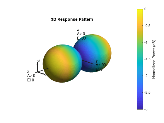
Next, draw a 3-D plot of the combined polarization response.

pattern(antenna,fc,-180:180,-90:90,'CoordinateSystem','polar', ...
    'Type','powerdb','Polarization','combined')

Figure contains an axes object. The hidden axes object with title 3D Response Pattern contains 13 objects of type surface, line, text, patch.

Compute the directivity of a crossed-dipole antenna element in several different directions.

Create a crossed-dipole antenna element System object™.

antenna = phased.CrossedDipoleAntennaElement;

Set the angles of interest to be at zero-degrees constant elevation angle. The seven azimuth angles are centered around boresight (zero degrees azimuth and zero degrees elevation). Set the desired frequency to 1 GHz.

ang = [-30,-20,-10,0,10,20,30; 0,0,0,0,0,0,0];
freq = 1e9;

Compute the directivity along the constant elevation cut.

d = directivity(antenna,freq,ang)
d = 7×1

    1.1811
    1.4992
    1.6950
    1.7610
    1.6950
    1.4992
    1.1811

Construct a crossed-dipole antenna element that operates in the frequency range from 100 MHz to 1.5 GHz. Then, plot the 3-D polar power pattern for the horizontal polarization component. Assume the antenna operates at 1 GHz.

antenna = phased.CrossedDipoleAntennaElement('FrequencyRange',[100 1500]*1e6);
fc = 1e9;
pattern(antenna,fc,-180:180,-90:90,'Type','powerdb', ...
    'CoordinateSystem','polar','Polarization','H')

Figure contains an axes object. The hidden axes object with title 3D Response Pattern contains 13 objects of type surface, line, text, patch.

Next, plot the vertical polarization component.

pattern(antenna,fc,-180:180,-90:90,'Type','powerdb', ...
    'CoordinateSystem','polar','Polarization','V')

Figure contains an axes object. The hidden axes object with title 3D Response Pattern contains 13 objects of type surface, line, text, patch.

Construct a crossed-dipole antenna element. Then, plot the pattern of the horizontal component of the field magnitude at an elevation angle of 0 degrees. Assume the antenna operating frequency is 1 GHz. Restrict the response to the range of azimuth angles from -70 to 70 degrees in 0.1 degree increments.

antenna = phased.CrossedDipoleAntennaElement('FrequencyRange',[0.5 1.5]*1e9);
fc = 1e9;
pattern(antenna,fc,-70:0.1:70,0,'Type','efield', ...
    'CoordinateSystem','polar','Polarization','combined')

Figure contains an axes object. The hidden axes object contains 3 objects of type line, text. This object represents 1 GHz .

Create a crossed-dipole antenna. Assume the antenna works between 1 and 2 GHz and its operating frequency is 1.5 GHz. Then, plot the directivity at a constant azimuth of 0.

antenna = phased.CrossedDipoleAntennaElement('FrequencyRange',[1e9 2e9]);
fc = 1.5e9;
pattern(antenna,fc,0,-90:90,'Type','directivity', ...
    'CoordinateSystem','rectangular')

Figure contains an axes object. The axes object with title Elevation Cut (azimuth angle = 0.0°), xlabel Elevation Angle (degrees), ylabel Directivity (dBi) contains an object of type line. This object represents 1.5 GHz.

The directivity is maximum at 0 elevation and attains a value of approximately 1.75 dB.

Plot the azimuth directivity pattern of a crossed-dipole antenna at two different elevations: 0 and30. Assume the operating frequency is 500 MHz.

fc = 500e6;
antenna = phased.CrossedDipoleAntennaElement('FrequencyRange',[100,900]*1e6);
patternAzimuth(antenna,fc,[0 30])

Figure contains an axes object. The hidden axes object contains 4 objects of type line, text. These objects represent 0.0 deg elevation Ⓐ , 30.0 deg elevation .

Plot a limited range of azimuth angles using the Azimuth parameter. Notice the change in scale.

patternAzimuth(antenna,fc,[0 30],'Azimuth',[-20:20])

Figure contains an axes object. The hidden axes object contains 4 objects of type line, text. These objects represent 0.0 deg elevation Ⓐ , 30.0 deg elevation .

Plot the elevation directivity pattern of a crossed-dipole antenna at two different azimuths: 45 and 55. Assume the operating frequency is 500 MHz.

fc = 500e6;
sCD = phased.CrossedDipoleAntennaElement('FrequencyRange',[100,900]*1e6);
patternElevation(sCD,fc,[45 55])

Figure contains an axes object. The hidden axes object contains 4 objects of type line, text. These objects represent 45.0 deg azimuth Ⓐ , 55.0 deg azimuth .

Plot a reduced range of elevation angles using the Elevation parameter. Notice the change in scale.

patternElevation(sCD,fc,[45 55],'Elevation',-20:20)

Figure contains an axes object. The hidden axes object contains 4 objects of type line, text. These objects represent 45.0 deg azimuth Ⓐ , 55.0 deg azimuth .

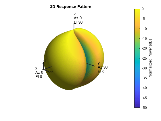
This example shows how to create a crossed-dipole antenna operating between 100 and 900 MHz and then how to plot its vertical and horizontal polarization response at 250 MHz in the form of a 3-D polar plot.

antenna = phased.CrossedDipoleAntennaElement(...
    'FrequencyRange',[100 900]*1e6);
pattern(antenna,250e6,-180:180,-90:90,'CoordinateSystem','polar','Polarization','V', ...
    'Type','powerdb')

Figure contains an axes object. The hidden axes object with title 3D Response Pattern contains 13 objects of type surface, line, text, patch.

The antenna pattern of the vertical-polarization component is almost isotropic and has a maximum at 0 elevation and 0 azimuth, as shown in the figure above.

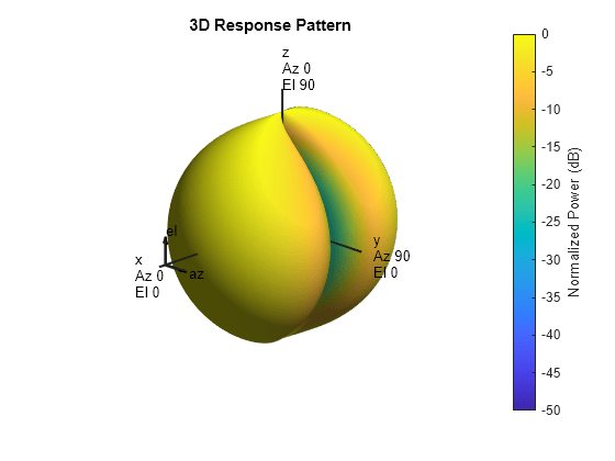
Plot the antenna's horizontal polarization response. The pattern of the horizontal polarization response also has a maximum at 0 elevation and 0 azimuth but no response at ±90 azimuth.

pattern(antenna,250e6,-180:180,-90:90,'CoordinateSystem','polar','Polarization','H', ...
    'Type','powerdb')

Figure contains an axes object. The hidden axes object with title 3D Response Pattern contains 13 objects of type surface, line, text, patch.

Show that the phased.CrossedDipoleAntennaElement antenna element supports polarization.

antenna = phased.CrossedDipoleAntennaElement;
isPolarizationCapable(antenna)
ans = logical
   1

The returned value of 1 shows that the crossed-dipole antenna element supports polarization.

Construct a crossed-dipole antenna element designed to operate in the frequency range from 100 MHz to 1.5 GHz. Assume the polarization is linear. Rotate the antenna by -45 degrees. Plot the 3-D polar power pattern for the horizontal and vertical polarization components at 1 GHz.

antenna = phased.CrossedDipoleAntennaElement('FrequencyRange',[100 1500]*1e6, ...
   'RotationAngle',-45.0,'Polarization','Linear');
fc = 1e9;
pattern(antenna,fc,-180:180,-90:90,'Type','powerdb','Normalize',false, ...
    'CoordinateSystem','polar','Polarization','H')

Figure contains an axes object. The hidden axes object with title 3D Response Pattern contains 13 objects of type surface, line, text, patch.

Next, plot the vertical polarization component.

pattern(antenna,fc,-180:180,-90:90,'Type','powerdb','Normalize',false, ...
    'CoordinateSystem','polar','Polarization','V')

Figure contains an axes object. The hidden axes object with title 3D Response Pattern contains 13 objects of type surface, line, text, patch.

Algorithms

The total response of a crossed-dipole antenna element is a combination of its frequency response and spatial response. phased.CrossedDipoleAntennaElement calculates both responses using nearest neighbor interpolation, and then multiplies the responses to form the total response.

References

[1] Mott, H., Antennas for Radar and Communications, John Wiley & Sons, 1992.

Extended Capabilities

Version History

Introduced in R2013a