Main Content

Multiple Explicit MPC Controllers

Multiple explicit MPC controllers

  • Multiple Explicit MPC Controllers block

Libraries:
Model Predictive Control Toolbox

Description

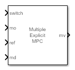
The Multiple Explicit MPC Controllers block uses the following input signals:

  • Measured plant outputs (mo)

  • Reference or setpoint (ref)

  • Measured plant disturbance (md), if any

  • Switching signal (switch)

The Multiple Explicit MPC Controllers block enables you to transition between multiple explicit MPC controllers in real time based on the current operating conditions. Typically, you design each controller for a particular region of the operating space. Using available measurements, you detect the current operating region and select the appropriate active controller using the switch inport.

The switching signal selects the active controller among a list of two or more candidate explicit MPC controllers. These controllers reduce online computational effort by using a table-lookup control law during each control interval instead of solving a quadratic programming problem. For more information, see Explicit MPC Controller.

To improve efficiency, inactive controllers do not evaluate their control law. However, to provide bumpless transfer between controllers, the inactive controllers continue to perform state estimation.

Like for the Multiple MPC Controllers block, you cannot disable evaluation for the Multiple Explicit MPC Controllers block. One controller must always be active.

Like the Explicit MPC Controller block, the Multiple Explicit MPC Controllers block supports only a subset of optional MPC features, as outlined in the following table.

Supported FeaturesUnsupported Features
  • Built-in (Kalman filter) and custom state estimation

  • Outport for state estimation results

  • External manipulated variable feedback signal inport

  • Single-precision block data (default is double precision)

  • Inherited sample time

  • Online tuning (penalty weight adjustments)

  • Online constraint adjustments

  • Online manipulated variable target adjustments

  • Reference and/or measured disturbance previewing

Examples

Ports

Input

expand all

Required Inputs

Use the switch input port to select the active controller. The switch input signal must be a scalar integer from 1 to Nc, where Nc is the number of specified candidate controllers. At each control instant, this signal designates the active controller. A switch value of 1 corresponds to the first entry in the cell array of candidate controllers, a value of 2 corresponds to the second controller, and so on.

If the switch signal is outside of the range 1 to Nc, the block retains the previous controller output.

Measured output signals, specified as a vector signal. The candidate controllers use the measured plant outputs to improve their state estimates.

All candidate controllers must use the same state estimation option, either default or custom. If your candidate controllers use default state estimation, you must connect the measured plant outputs to the mo input port. If your candidate controllers use custom state estimation, you must connect the estimated plant state signal to the x[k|k] input port.

Dependencies

To enable this port, clear the Use custom state estimation instead of using the built-in Kalman filter parameter.

Custom state estimate, specified as a vector signal. The candidate controllers use the connected state estimates instead of estimating the states using the built-in estimator. Use custom state estimates when an alternative estimation technique is considered superior to the built-in estimator or when the states are fully measurable.

All candidate controllers must use the same state estimation option, either default or custom. If your candidate controllers use custom state estimation, you must connect current state estimates to the x[k|k] input port. If your candidate controllers use default state estimation, you must connect the measured outputs to the mo input port.

When you use custom state estimation, all candidate controllers must have the same dimensions. All candidate controllers must use the same state definitions (number and order of states) for their respective plant, disturbance, and measurement noise models.

Dependencies

To enable this port, select the Use custom state estimation instead of using the built-in Kalman filter parameter.

At each control instant, the ref signal must contain the current reference values (targets or setpoints) for the ny output variables, where ny is the total number of outputs, including measured and unmeasured outputs. Since this block does not support reference previewing, ref must be a vector signal.

Additional Inputs

If your controller prediction model has measured disturbances, you must enable this port and connect to it a row vector signal containing Nmd elements, where Nmd is the number of measured disturbances.

Since this block does not support measured disturbance previewing, md must be a vector signal.

Dependencies

To enable this port, select the Measured disturbances parameter.

Control signals used in the plant at the previous control interval, specified as a vector signal of length Nmv, where Nmv is the number of manipulated variables. All candidate controllers use this signal to update their controller state estimates at each control interval. This helps minimize bumpless transfer when the driving controller is switched. Using this input also improves state estimation accuracy when the manipulated variables (MV) vector used in the plant differs from the MV vector calculated by the block, for example, due to signal saturation or an override condition.

Controller state estimation assumes that the MV vector is piecewise constant. Therefore, at time tk, the ext.mv value must be the effective MV vector between times tk–1 and tk. For example, if the MVs are actually varying over this interval, you might supply the time-averaged value evaluated at time tk.

Note

  • Connect ext.mv to the MV signals actually applied to the plant in the previous control interval. Typically, these MV signals are the values generated by the driving controller block, though this is not always the case. If the controller block is not driving the plant, then feeding the actual control signal to ext.mv can also help achieve bumpless transfer when the controller is switched back online.

  • Using this option when the controller is driving the plant can cause an algebraic loop in the Simulink® model, since there is direct feedthrough from the ext.mv input to the mv outport. To prevent such algebraic loops, insert a Memory block or Unit Delay block.

For an example that uses the external manipulated variable input port for bumpless transfer, see Switch Controller Online and Offline with Bumpless Transfer.

Dependencies

To enable this port, select the External manipulated variable parameter.

Output

expand all

Required Output

Optimal manipulated variable control action, returned as a column vector signal of length Nmv, where Nmv is the number of manipulated variables.

The Multiple Explicit MPC Controllers block passes the output of the active controller to the mv output. Therefore, the active controller updates the mv output at each control instant using the control law contained in its explicit MPC controller object. If the control law evaluation fails, this signal is unchanged; that is, it is held at the previous successful result.

Additional Outputs

This output indicates whether the latest explicit MPC control-law evaluation succeeded. The outport provides a scalar signal that has one of the following values:

  • 1 — Successful explicit control law evaluation

  • 0 — Failure due to one or more control law parameters out of range

  • –1 — Control law parameters were within the valid range but an extrapolation was necessary

If status is either 0 or –1, the mv outport remains at the last known good value.

Dependencies

To enable this port, select the Status of piecewise affine function evaluation parameter.

This output provides the index of the polyhedral region used in the latest explicit control law evaluation. If the control law evaluation fails, the signal at this outport is zero.

Dependencies

To enable this port, select the Region number of evaluated piecewise affine function parameter.

Estimated controller states at each control instant, returned as a vector signal. The estimated states include the plant, disturbance, and noise model states. If custom state estimation is used, this output signal has the same value as the x[k|k] input signal.

Dependencies

To enable this port, select the Estimated controller states parameter.

Parameters

expand all

Candidate controllers, specified as one of the following:

  • Cell array of explicitMPC objects

  • Cell array of strings or a cell array of character vectors, where each element is the name of an explicitMPC object in the MATLAB® workspace

The specified array must contain at least two candidate controllers. The first entry in the cell array is the controller that corresponds to a switch input value of 1, the second corresponds to a switch input value of 2, and so on.

Programmatic Use

Block Parameter: empcobjs
Type: string, character vector, cell array of strings, cell array of character vectors
Default: ""

Initial states for the candidate controllers, specified as one of the following:

  • Cell array of mpcstate objects.

  • Cell array of strings or a cell array of character vectors, where each element is the name of an mpcstate object in the MATLAB workspace.

  • {[],[],...}, {'[]','[]',...}, or {"[]","[]",...} — Use the nominal condition defined in Model.Nominal property of each candidate controller as its initial state.

If you leave this parameter blank, the block uses the nominal values defined in the Model.Nominal property of the explicitMPC objects. You can use this parameter to make the controller states reflect the true plant environment at the start of your simulation to the best of your knowledge.

If custom state estimation is enabled, the block ignores Cell Array of Initial Controller States parameter.

Programmatic Use

Block Parameter: x0s
Type: string, character vector, cell array of strings, cell array of character vectors
Default: ""
General Tab

If your controller has measured disturbances, you must select this parameter to add the md output port to the block.

Programmatic Use

Block Parameter: md_inport_multiple
Type: string, character vector
Values: "off", "on"
Default: "on"

Select this parameter to add the ext.mv input port to the block.

Programmatic Use

Block Parameter: mv_inport_multiple
Type: string, character vector
Values: "off", "on"
Default: "off"

Select this parameter to add the status output port to the block.

Programmatic Use

Block Parameter: return_status_multiple
Type: string, character vector
Values: "off", "on"
Default: "off"

Select this parameter to add the region output port to the block.

Programmatic Use

Block Parameter: return_region_multiple
Type: string, character vector
Values: "off", "on"
Default: "off"

Select this parameter to add the est.state output port to the block.

Programmatic Use

Block Parameter: return_state_multiple
Type: string, character vector
Values: "off", "on"
Default: "off"

Select this parameter to remove the mo input port and add the x[k|k] input port.

Programmatic Use

Block Parameter: state_inport_multiple
Type: string, character vector
Values: "off", "on"
Default: "off"
Others Tab

Specify the block data type of the manipulated variables as one of the following:

  • double — Double-precision floating point

  • single — Single-precision floating point

    If you are implementing the block on a single-precision target, specify the output data type as single.

  • data type expression — An expression that evaluates to either double or single. For more information see Control Data Types of Signals (Simulink).

Programmatic Use

Block Parameter: BlockDataType_multiple
Type: string, character vector
Values: "double", "single", data type expression
Default: "double"

Select this parameter to inherit the sample time of the parent subsystem as the block sample time. Doing so allows you to conditionally execute this block inside Function-Call Subsystem (Simulink) or Triggered Subsystem (Simulink) blocks. For an example, see Using MPC Controller Block Inside Function-Call and Triggered Subsystems.

Note

You must execute Function-Call Subsystem or Triggered Subsystem blocks at the sample rate of the controller. Otherwise, you can see unexpected results for two reasons.

  • The first element of the MV rate vector (which is the difference between the current and the last value of the manipulated variable) is normally weighted and constrained assuming that the last MV value occurred in the past at the sample time specified in the MPC object, and when the block is executed with a different sample rate, this assumption no longer holds.

  • The built-in Kalman estimator uses the sample time specified in the MPC object to provide an estimation of the current state to the MPC optimization problem, so when the block is executed with a different sample time, the estimated state is no longer correct.

If you clear this parameter (default), the sample time of the block is inherited from the controller object.

To view the sample time of a block, in the Simulink model window, on the Debug tab, under Information Overlays, select either colors or Text. For more information, see View Sample Time Information (Simulink).

Programmatic Use

Block Parameter: SampleTimeInherited_multiple
Type: string, character vector
Values: "off", "on"
Default: "off"

Extended Capabilities

C/C++ Code Generation
Generate C and C++ code using Simulink® Coder™.

PLC Code Generation
Generate Structured Text code using Simulink® PLC Coder™.

Version History

Introduced in R2016b