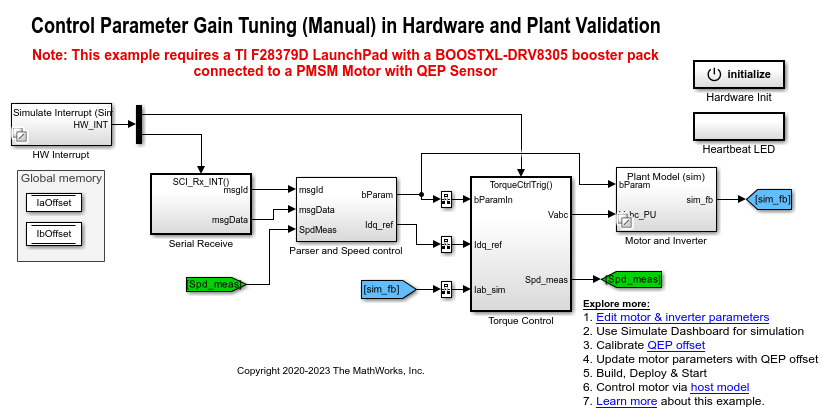
Tune Control Parameter Gains in Hardware and Validate Plant
This example uses field-oriented control (FOC) to run a three-phase permanent magnet synchronous motor (PMSM) in different modes of operation for plant validation. FOC algorithm implementation needs the real-time feedback of the rotor position. This example uses a quadrature encoder sensor to measure the rotor position. For details about FOC, see Field-Oriented Control.
The example runs the motor in these modes:
Stop - In this mode, the motor stops running because the inverter outputs zero volts.
Open loop - In this mode, the controller uses open-loop control to run the motor. You can use the Operating Mode Variables > Open-loop mode area of the host model to change the output voltage of the inverter (in per-unit) and the rotor speed (in per-unit). Use the Monitor area to select the speed and rotor position values to display them on the scope for monitoring.
Torque control - In this mode, the controller uses a torque control algorithm to run the motor. You can use the Operating Mode Variables > Motor torque control mode area of the host model to change the
 reference and
  reference current values (in per-unit). You can also set the maximum speed limit of the motor (in per-unit).
You can lock the rotor by turning the slider switch to the Pos lock position that sets the rotor position to zero. Therefore, in this mode, the controller receives the position feedback as zero because the motor stops running. If you turn the switch to the Unlock position, the motor runs and the controller receives position feedback from the quadrature encoder (you can monitor this value by using the Position_meas signal in the Monitor area of host model). You can use the scope to monitor the two debug signals (Monitor Signal #1 and Monitor Signal #2) that you select in the Monitor area. Therefore, you can use the slider switch to tune the torque control gain parameters.
Speed control - In this mode, the controller uses a speed control algorithm to run the motor. You can use the Operating Mode Variables > Motor speed control mode area of the host model to change the Speed Reference value (in per-unit) of the rotor. You can use the scope to monitor the two debug signals (Monitor Signal #1 and Monitor Signal #2) that you select in the Monitor area.
For information related to the per-unit system, see Per-Unit System.
To further control the motor, you can also use the Control loop gains area of the host model to change the control parameters of the d-axis and q-axis current controllers and the speed controller.
You can use this example to run the motor in open-loop control, torque control, and speed control modes. You can also use this example for tuning the hardware gains and validating the plant model.
Caution: Stop the motor first before transitioning from one operating mode to another.
You can select one of these operating modes in the Control area of the host model:
Stop
Open loop run
Torque control
Speed control
Model
The example includes the model mcb_pmsm_operating_mode_f28379d.
You can use the model for both simulation and code generation.
Required MathWorks Products
To simulate model:
Motor Control Blockset™
To generate code and deploy model:
1. Motor Control Blockset™
2. Embedded Coder®
3. C2000™ Microcontroller Blockset
4. Fixed-Point Designer™ (only needed for optimized code generation)
Prerequisites
1. Obtain the motor parameters. We provide default motor parameters with the Simulink® model that you can replace with the values from either the motor datasheet or other sources.
However, if you have the motor control hardware, you can estimate the parameters for the motor that you want to use, by using the Motor Control Blockset parameter estimation tool. For instructions, see Estimate Motor Parameters Using Motor Control Blockset Parameter Estimation Tool.
The parameter estimation tool updates the motorParam variable (in the MATLAB® workspace) with the estimated motor parameters.
2. If you obtain the motor parameters from the datasheet or other sources, update the motor parameters and inverter parameters in the model initialization script associated with the Simulink® models. For instructions, see Estimate Control Gains and Tune Control Parameters.
If you use the parameter estimation tool, you can update the inverter parameters, but do not update the motor parameters in the model initialization script. The script automatically extracts motor parameters from the updated motorParam workspace variable.
Simulate Model
Follow these steps to simulate the model.
1. Open the target model included with this example.
2. Click Run on the Simulation tab to simulate the target model.
3. Open the mcb_pmsm_operating_mode_f28379d > Simulate Dashboard subsystem.

Instructions for Open-Loop Run Mode:
1. If the current operating mode is other than open-loop run, select Stop in the Control area to stop the motor. Select Open loop run to start the motor.
2. Set the reference voltage and reference speed values (in per-unit) in the Voltage ref (PU) and Speed ref (PU) fields available in the Operating Mode Variables > Open-loop mode area.
Instructions for Torque Control Mode:
1. If the current operating mode is other than torque control, select Stop in the Control area to stop the motor. Select Torque control in the Control area.
2. Enter the value 0 (per-unit) in the Iq Reference field in the Operating Mode Variables > Motor torque control mode area. In addition, set the speed limit of the motor using the Speed limit field.
3. Move the slider switch to Unlock position in the Operating Mode Variables > Motor torque control mode area.
4. Enter the value 0.1 (per-unit) in the Iq Reference field (in the Operating Mode Variables area) to start running the motor.
5. Open Simulation Data Inspector and select the Iq_ref_PU and Iq_fb_PU signals for monitoring.
6. Follow steps 2 to 5 for Id Reference and monitor the Id_ref_PU and Id_fb_PU signals.
NOTE: The motor can reach high speeds if you run it under no load condition in this operating mode. In addition, the motor will not meet the Iq reference current under no load condition in this operating mode.
Instructions for Speed Control Mode:
1. If the current operating mode is other than speed control, select Stop in the Control area to stop the motor. Select Speed control in the Control area.
2. Enter the value 0.5 (per-unit) in the Speed Reference field in the Operating Mode Variables > Motor speed control mode area.
3. Open Simulation Data Inspector and select the Speed_ref_PU and Speed_fb_PU signals for monitoring.
Instructions for Tuning Gain of Torque Controller:
1. If the current operating mode is other than torque control, select Stop in the Control area to stop the motor. Select Torque control in the Control area.
2. Turn the slider switch to Pos lock position in the Operating Mode Variables > Motor torque control mode area.
3. Enter the value 0.2 (per-unit) in the Id Reference field in the Operating Mode Variables area.
4. Open Simulation Data Inspector, select the Id_ref_PU and Id_fb_PU signals, and observe the step response of these signals.
5. Tune the control gains Kp and Ki for the d-axis current controller. Perform step change to validate the controller gains.
Instructions for Tuning Gain of Speed Controller:
1. If the current operating mode is other than speed control, select Stop in the Control area to stop the motor. Select Speed control in the Control area.
2. Enter the value 0.5 (per-unit) in the Speed Reference field in the Operating Mode Variables > Motor speed control mode area.
3. Enter the value 0.8 (per-unit) in the Speed Reference field.
4. Open Simulation Data Inspector, select the Speed_ref_PU and Speed_fb_PU signals, and observe the speed step response.
5. Tune the control gains Kp and Ki for the speed controller. Perform step change to validate the controller gains.
Generate Code and Deploy Model to Target Hardware
This section instructs you to generate code and run the FOC algorithm on the target hardware.
The example uses a host and a target model. The host model is a user interface to the controller hardware board. You can run the host model on the host computer. The prerequisite to use the host model is to deploy the target model to the controller hardware board. The host model uses serial communication to command the model, run (and control) the motor in a selected operating mode, and monitor the debug signals of the model.
Required Hardware
The example supports this hardware configuration. You can also use the target model name to open the model for the corresponding hardware configuration, from the MATLAB® command prompt.
LAUNCHXL-F28379D controller + BOOSTXL-DRV8305 inverter:
mcb_pmsm_operating_mode_f28379d
For connections related to the preceding hardware configuration, see LAUNCHXL-F28069M and LAUNCHXL-F28379D Configurations.
Generate Code and Run Model on Target Hardware
1. Simulate the target model and observe the simulation results.
2. Complete the hardware connections.
3. The model automatically computes the ADC (or current) offset values. To disable this functionality (enabled by default), update the value 0 to the variable inverter.ADCOffsetCalibEnable in the model initialization script.
Alternatively, you can compute the ADC offset values and update it manually in the model initialization scripts. For instructions, see Run 3-Phase AC Motors in Open-Loop Control and Calibrate ADC Offset.
4. Compute the quadrature encoder index offset value and update it in the model initialization scripts associated with the target model. For instructions, see Quadrature Encoder Offset Calibration for PMSM.
5. Open the target model for the hardware configuration that you want to use. If you want to change the default hardware configuration settings for the model, see Model Configuration Parameters.
6. To ensure that CPU2 is not mistakenly configured to use the board peripherals intended for CPU1, load a sample program to CPU2 of LAUNCHXL-F28379D, for example, program that operates the CPU2 blue LED by using GPIO31 (c28379D_cpu2_blink.slx). For more information about the sample program or model, see the Task 2 - Create, Configure and Run the Model for TI Delfino F28379D LaunchPad (Dual Core) section in Getting Started with Texas Instruments C2000 Microcontroller Blockset (C2000 Microcontroller Blockset).
NOTE:
Do not directly switch between the open-loop run, torque control, and speed control operating modes. Always stop the motor before changing the operating mode.
Before you run the motor in speed control mode for the first time, run the motor in open-loop to determine the quadrature encoder index. This helps to start the motor smoothly in the closed-loop speed control mode.
Instructions for Open-Loop Run Mode:
1. Click Build, Deploy & Start on the Hardware tab to deploy the target model to the hardware.
2. Click the mcb_host_mode_control.slx host model hyperlink in the target model to open the associated host model.
3. In the model initialization script associated with the target model, specify the communication port using the variable target.comport. The example uses this variable to update the Port parameter of the Host Serial Setup, Host Serial Receive, and Host Serial Transmit blocks available in the host model.
4. Click Run on the Simulation tab to run the host model.
5. Select Stop in the Control area to stop the motor.
6. Select Open loop run to start the motor.
7. Set the reference voltage and reference speed values (in per-unit) in the Voltage ref (PU) and Speed ref (PU) fields available in the Operating Mode Variables > Open-loop mode area.
Instructions for Torque Control Mode:
1. Click Build, Deploy & Start on the Hardware tab to deploy the target model to the hardware.
2. Click the mcb_host_mode_control.slx host model hyperlink in the target model to open the associated host model.
3. In the model initialization script associated with the target model, specify the communication port using the variable target.comport. The example uses this variable to update the Port parameter of the Host Serial Setup, Host Serial Receive, and Host Serial Transmit blocks available in the host model.
4. Click Run on the Simulation tab to run the host model.
5. Select Stop in the Control area to stop the motor.
6. Enter the value 0 (per-unit) in the Id Ref (PU) and Iq Ref (PU) fields in the Operating Mode Variables > Motor torque control mode area. In addition, set the speed limit of the motor using the Speed limit (PU) field.
7. Select Torque control in the Control area.
8. Move the slider switch to Unlock position in the Operating Mode Variables > Motor torque control mode area.
9. Select Iq_ref for Monitor Signal #1 and Iq_meas for Monitor Signal #2 in the Monitor area.
10. Enter the value 0.1 (per-unit) in the Iq Ref (PU) field (in the Operating Mode Variables area) to start running the motor.
11. Open the scope in the host model and monitor the Iq_ref and Iq_meas current signals.
Note: The motor can reach high speeds if you run it under no load condition in this operating mode. In addition, the motor will not meet the Iq reference current under no load condition in this operating mode.
Instructions for Speed Control Mode:
1. Click Build, Deploy & Start on the Hardware tab to deploy the target model to the hardware.
2. Click the mcb_host_mode_control.slx host model hyperlink in the target model to open the associated host model.
3. In the model initialization script associated with the target model, specify the communication port using the variable target.comport. The example uses this variable to update the Port parameter of the Host Serial Setup, Host Serial Receive, and Host Serial Transmit blocks available in the host model.
4. Click Run on the Simulation tab to run the host model.
5. Select Stop in the Control area to stop the motor.
6. Enter the value 0.5 (per-unit) in the Speed Ref (PU) field in the Operating Mode Variables > Motor speed control mode area.
7. Select Speed control in the Control area.
8. Select Speed_ref for Monitor Signal #1 and Speed_meas for Monitor Signal #2 in the Monitor area.
9. Open the scope in the host model and monitor the Speed_ref and Speed_meas output signals.
Instructions for Tuning Gain of Torque Controller:
1. Click Build, Deploy & Start on the Hardware tab to deploy the target model to the hardware.
2. Click the mcb_host_mode_control.slx host model hyperlink in the target model to open the associated host model.
3. In the model initialization script associated with the target model, specify the communication port using the variable target.comport. The example uses this variable to update the Port parameter of the Host Serial Setup, Host Serial Receive, and Host Serial Transmit blocks available in the host model.
4. Click Run on the Simulation tab to run the host model.
5. Select Stop in the Control area to stop the motor.
6. Select Torque control in the Control area.
7. Turn the slider switch to Pos lock position in the Operating Mode Variables > Motor torque control mode area.
8. Select Id_ref for Monitor Signal #1 and Id_meas for Monitor Signal #2 in the Monitor area.
9. Enter the value 0.2 (per-unit) in the Id Ref (PU) field in the Operating Mode Variables area.
10. Open the scope and monitor the step response signal.
11. Tune the control gains Kp and Ki for the d-axis current controller.
Instructions for Tuning Gain of Speed Controller:
1. Click Build, Deploy & Start on the Hardware tab to deploy the target model to the hardware.
2. Click the mcb_host_mode_control.slx host model hyperlink in the target model to open the associated host model.
3. In the model initialization script associated with the target model, specify the communication port using the variable target.comport. The example uses this variable to update the Port parameter of the Host Serial Setup, Host Serial Receive, and Host Serial Transmit blocks available in the host model.
4. Click Run on the Simulation tab to run the host model.
5. Select Stop in the Control area to stop the motor.
6. Select Speed control in the Control area.
7. Select Speed_ref for Monitor Signal #1 and Speed_meas for Monitor Signal #2 in the Monitor area.
8. Enter the value 0.5 (per-unit) in the Speed Ref (PU) field in the Operating Mode Variables > Motor speed control mode area.
9. Open the scope and observe the reference and the measured speed values.
10. Enter the value 0.8 (per-unit) in the Speed Ref (PU) field.
11. Observe the speed step response in the scope.
12. Tune the control gains Kp and Ki for the speed controller.
Instructions for Validating Plant Model:
1. Open the target model included with this example.
2. Click Run on the Simulation tab to simulate the target model.
3. Open the mcb_pmsm_operating_mode_f28379d > Simulate Dashboard subsystem.
4. If the current operating mode is other than speed control, select Stop in the Control area to stop the motor. Select Speed control in the Control area.
5. Enter the value 0.2 (per-unit) in the Speed Reference field in the Operating Mode Variables > Motor speed control mode area.
6. Enter the value 0.5 (per-unit) in the Speed Reference field.
7. Open Simulation Data Inspector, select the Speed_ref_PU and Speed_fb_PU signals, and observe the speed step response.
8. Click Build, Deploy & Start on the Hardware tab to deploy the target model to the hardware.
9. Click the mcb_host_mode_control.slx host model hyperlink in the target model to open the associated host model.

10. In the model initialization script associated with the target model, specify the communication port using the variable target.comport. The example uses this variable to update the Port parameter of the Host Serial Setup, Host Serial Receive, and Host Serial Transmit blocks available in the host model.
11. Click Run on the Simulation tab to run the host model.
12. Select Stop in the Control area of the host model to ensure that the motor is not running.
13. Select Speed control in the Control area.
14. Select Speed_ref for Monitor Signal #1 and Speed_meas for Monitor Signal #2 in the Monitor area.
15. Enter the value 0.2 (per-unit) in the Speed Ref (PU) field in the Operating Mode Variables > Motor speed control mode area.
16. Open the scope and observe the reference and the measured speed values.
17. Enter the value 0.5 (per-unit) in the Speed Ref (PU) field.
18. Observe the speed step response in the scope.
19. Compare the speed step responses obtained in steps 7 (with simulation) and 18 (with code generation).
NOTE: In the Control loop gains area, you must enter the gain values that can be represented by the datatype defined in the model initialization script.
For details about the serial communication between the host and target models, see Host-Target Communication.