PDSCH Throughput for Non-Codebook Based Precoding Schemes: Port 5 (TM7), Port 7 or 8 or Port 7-8 (TM8), Port 7-14 (TM9 and TM10)
This example demonstrates how to measure the Physical Downlink Shared Channel (PDSCH) throughput performance using LTE Toolbox™ for the following non-codebook based precoding transmission modes (TM):
TM7: non-codebook based precoding for single layer (Port 5)
TM8: non-codebook based precoding for up to two layers (dual layer Port 7-8, or single antenna port, port 7 or 8)
TM9 and TM10: non-codebook based precoding for up to eight layers Port 7-14 or single antenna port, port 7 or 8
FDD and TDD duplexing schemes are supported. The example also shows how to parameterize and customize the settings for the different transmission modes. It also supports the use of Parallel Computing Toolbox™ to reduce effective simulation time.
Introduction
This example measures throughput for a number of SNR points. The provided code can operate under a number of transmission modes: TM7, TM8, TM9 and TM10. FDD and TDD duplexing schemes are supported. For information on how to model TM1, TM2, TM3, TM4 and TM6 check the following example: PDSCH Throughput Conformance Test for Single Antenna (TM1), Transmit Diversity (TM2), Open Loop (TM3) and Closed Loop (TM4/6) Spatial Multiplexing
Since non-codebook based TMs are considered, the precoding (beamforming) matrix must be calculated. This is achieved using a singular value decomposition (SVD) approach. Perfect knowledge of the channel is assumed.
For each of the considered SNR points, operating on a subframe by subframe basis:
The precoding (beamforming) matrix is calculated from a perfect channel estimate.
A populated resource grid is generated and OFDM modulated to create the waveform to transmit.
The generated waveform is passed through a noisy fading channel.
Receiver operations (channel estimation, equalization, demodulation and decoding) are performed.
The throughput performance of the PDSCH is determined using the block CRC result at the output of the channel decoder.
A parfor loop can be used instead of the for loop for the SNR calculation. This is indicated within the example. The parfor statement is part of the Parallel Computing Toolbox and executes the SNR loops in parallel to reduce the total simulation time.
Simulation Configuration
The example is executed for a simulation length of NFrames = 2 frames for a number of SNR points. A large number of NFrames should be used to produce meaningful throughput results. SNRIn can be an array of values or a scalar. Some TMs and certain modulation schemes are more robust to noise and channel impairments than others, therefore different values of SNR may have to be used for different parameter sets.
NFrames = 2;        % Number of frames

SNRIn = [-4 1];     % SNR range in dB
A set of common parameters for all TMs is initially specified, these include the bandwidth, the desired code rate, the modulation scheme and the allocated set of resource blocks. Not specifying an RMC number ensures that all downlink subframes are scheduled. If RMC is specified (e.g. 'R.0'), the subframe scheduling is as defined in TS 36.101 [ 1 ].
The variable txMode selects the TM via a switch statement. For each TM, the required parameters are specified. This example does not perform DCI format decoding, so the DCIFormat field is not strictly necessary. However, since the DCI format is closely linked to the TM, it is included for completeness.
For the purpose of this example, TM9 and TM10 are the same, except for the DCI format, however, they are separated in the switch statement for completeness.
Once the basic set of parameters have been specified, a call to lteRMCDL is needed to fully populate the downlink parameter structure enb.
simulationParameters = []; % clear simulationParameters
simulationParameters.NDLRB = 50;
simulationParameters.PDSCH.TargetCodeRate = 0.5;
simulationParameters.PDSCH.Modulation = {'16QAM'};
simulationParameters.PDSCH.PRBSet = (0:9)';

txMode = 'TM8';     % TM7, TM8, TM9, TM10
DuplexMode = 'TDD'; % 'FDD', 'TDD'

switch txMode
    case 'TM7' % single layer (Port 5)
        simulationParameters.PDSCH.DCIFormat = 'Format1';
        simulationParameters.PDSCH.TxScheme = 'Port5';
        simulationParameters.PDSCH.NLayers = 1;
        ntxants = 4;
    case 'TM8' % up to two layers (dual layer Port 7-8, or single antenna
               % port, port 7 or 8)
        simulationParameters.PDSCH.DCIFormat = 'Format2B';
        simulationParameters.PDSCH.TxScheme = 'Port7-8'; %'Port7-8','Port8'
        simulationParameters.PDSCH.NLayers = 2;
        ntxants = 4;
        simulationParameters.PDSCH.NSCID = 0;
    case 'TM9' % up to eight layers (up to eight layers Port 7-14 or single
               % antenna port, port 7 or 8)
        simulationParameters.PDSCH.DCIFormat = 'Format2C';
        simulationParameters.PDSCH.TxScheme = 'Port7-14';
        simulationParameters.PDSCH.NLayers = 4;
        ntxants = 8;
        simulationParameters.CSIRefP = ntxants;
    case 'TM10' % up to eight layers (up to eight layers Port 7-14 or
                % single antenna port, port 7 or 8)
        simulationParameters.PDSCH.DCIFormat = 'Format2D';
        simulationParameters.PDSCH.TxScheme = 'Port7-14';
        simulationParameters.PDSCH.NLayers = 4;
        ntxants = 8;
        simulationParameters.CSIRefP = ntxants;
    otherwise
        error('Transmission mode should be one of TM7, TM8, TM9 or TM10.')
end

% For 2 codewords (more than 4 layers), the modulation field needs two values, one per codeword
if (simulationParameters.PDSCH.NLayers > 4) && (length(simulationParameters.PDSCH.Modulation)<2)
    simulationParameters.PDSCH.Modulation = repmat(simulationParameters.PDSCH.Modulation,1,2);
end
The size of the precoding matrix W (beamforming matrix) is NLayers -by- ntxants. The number of transmit antennas is taken from W in subsequent toolbox function calls. The number of receive antennas is specified later on as part of the propagation channel.
% Initialize W to zero
simulationParameters.PDSCH.W = zeros(simulationParameters.PDSCH.NLayers, ntxants);
Set the duplexing mode and specify the number of subframes to 1. The code generates one subframe at a time repeatedly until a total of NFrames are generated.
simulationParameters.DuplexMode = DuplexMode;
simulationParameters.TotSubframes = 1;
Call the lteRMCDL function to generate the default eNodeB parameters not specified in simulationParameters. These will be required later to generate the waveform using lteRMCDLTool.
enb = lteRMCDL(simulationParameters);
The output enb structure contains, amongst other fields, the transport block sizes and redundancy version sequence for each codeword subframe within a frame. These are used later in the simulation.
trBlkSizes = enb.PDSCH.TrBlkSizes;
rvSequence = enb.PDSCH.RVSeq;
The number of codewords, ncw, is the number of entries in the enb.PDSCH.Modulation field.
ncw = length(string(enb.PDSCH.Modulation));
Print a summary of some of the more relevant simulation parameters. Confirm the parameter settings align with expected values. The reported code rate displayed can be useful to detect problems when manually specifying the transport block sizes. Typical values are 1/3, 1/2 and 3/4.
hDisplayENBParameterSummary(enb, txMode);
-- Parameter summary: --------------------------------------------
                      Duplexing mode: TDD
                   Transmission mode: TM8
                 Transmission scheme: Port7-8
  Number of downlink resource blocks: 50
 Number of allocated resource blocks: 10
Cell-specific reference signal ports: 1
         Number of transmit antennas: 4
                 Transmission layers: 2
                 Number of codewords: 1
               Modulation codeword 1: 16QAM
    Transport block sizes codeword 1:     4584    4008       0       0    4584    4584    4008       0       0    4584
                Code rate codeword 1:   0.5053  0.4941       0       0  0.5053  0.5053  0.4941       0       0  0.5053
------------------------------------------------------------------
Propagation Channel and Channel Estimator Configuration
The structure channel contains the channel model configuration parameters.
channel = struct;                    % Channel config structure
channel.Seed = 6;                    % Channel seed
channel.NRxAnts = 8;                 % Number of receive antennas
channel.DelayProfile ='EPA';         % Delay profile
channel.DopplerFreq = 5;             % Doppler frequency
channel.MIMOCorrelation = 'Low';     % Multi-antenna correlation
channel.NTerms = 16;                 % Oscillators used in fading model
channel.ModelType = 'GMEDS';         % Rayleigh fading model type
channel.InitPhase = 'Random';        % Random initial phases
channel.NormalizePathGains = 'On';   % Normalize delay profile power
channel.NormalizeTxAnts = 'On';      % Normalize for transmit antennas
% The channel sampling rate depends on the FFT size used in the OFDM
% modulator. This can be obtained using the function lteOFDMInfo.
ofdmInfo = lteOFDMInfo(enb);
channel.SamplingRate = ofdmInfo.SamplingRate;

% Maximum channel delay (multipath and channel filtering)
channel.InitTime = 0;
[~,chInfo] = lteFadingChannel(channel,0); % get channel info
maxChDelay = ceil(max(chInfo.PathSampleDelays)) + chInfo.ChannelFilterDelay;
Define the channel estimator configuration structure. Since non-codebook based TMs are used, set the DMRS as reference signal for channel estimation.
cec = struct;                        % Channel estimation config structure
cec.PilotAverage = 'UserDefined';    % Type of pilot symbol averaging
cec.FreqWindow = 41;                 % Frequency window size
cec.TimeWindow = 27;                 % Time window size
cec.InterpType = 'Cubic';            % 2D interpolation type
cec.InterpWindow = 'Centered';       % Interpolation window type
cec.InterpWinSize = 1;               % Interpolation window size
cec.Reference = 'DMRS';              % Use DMRS as reference signal
Display Simulation Information
The variable displaySimulationInformation controls the display of simulation information such as the HARQ process ID used for each subframe. In case of CRC error, the value of the index to the RV sequence is also displayed.
displaySimulationInformation = true;
Processing Chain
To determine the throughput at each SNR point, the subframe by subframe PDSCH processing chain includes:
Calculating the Precoding Matrix - A perfect channel estimate is used to calculate the precoding matrix. The calculation process differs slightly between FDD and TDD. A detailed explanation of this step is provided in the next section.
Updating Current HARQ Process - The HARQ process either carries new transport data or a retransmission of previously sent transport data depending upon the Acknowledgment (ACK) or Negative Acknowledgment (NACK) based on CRC results. All this is handled by the HARQ scheduler, hHARQScheduling.m. The PDSCH data is updated based on the HARQ state.
Creating Transmit Waveform - Pass the data generated by the HARQ process to the
lteRMCDLToolfunction to produce an OFDM modulated waveform, containing the physical channels and signals.
Noisy Channel Modeling - Pass the waveform through a fading channel and add noise (AWGN).
Performing Synchronization and OFDM Demodulation - Offset the received symbols to account for a combination of implementation delay and channel delay spread. OFDM demodulate the symbols.
Performing Channel Estimation - Estimate the channel response and noise level. Use these estimates to decode the PDSCH.
Decoding the PDSCH - Obtain an estimate of the received codewords using
ltePDSCHDecodeto demodulate and descramble the recovered PDSCH symbols for all transmit and receive antenna pairs.
Decoding the Downlink Shared Channel (DL-SCH) and Storing the Block CRC Error for a HARQ Process - Pass the vector of decoded soft bits to
lteDLSCHDecode, which decodes the codeword and returns the block CRC error used to determine the throughput of the system. The contents of the new soft buffer,harqProc(harqID).decState, is available at the output of this function to be used when decoding the next subframe.
Precoding Matrix Calculation
Since non-codebook based TMs are modeled, the precoding (beamforming) matrix must be computed, which is based on the channel estimate. For simplicity, perfect knowledge of the channel is assumed.
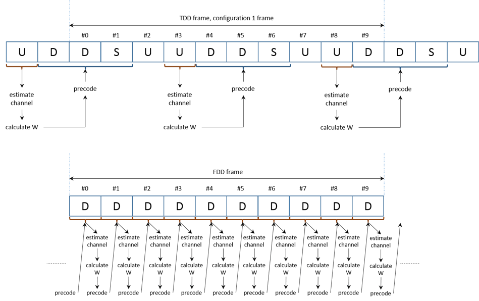
The figure shows the timing associated with the channel estimation, precoding matrix W calculation and precoding operation for both FDD and TDD modes.
For TDD (uplink-downlink configuration 1 frame structure), the channel is estimated in the last UL subframe before a DL subframe. This channel estimate is used to calculate the precoding matrix W. All subsequent DL subframes (including special subframes) until the next UL subframe are precoded with this matrix W.
For FDD, there is a delay of one subframe between the calculation of the precoding matrix W and the subframe where it is used. For example, the precoding matrix used in subframe n has been calculated with the channel estimate obtained in subframe n-1, as shown in the figure.
The function hCalculatePrecodingMatrix calculates W by:
Obtaining a perfect channel estimate for the considered subframe
Averaging the channel estimates for all the allocated RBs
Calculating the singular value decomposition and extracting the first
NLayerscolumns to obtain the precoding vector.
If desired, a different calculation or value of W can be used here instead of the call to hCalculatePrecodingMatrix.m.
This figure shows the channel estimation averaging process and W calculation.
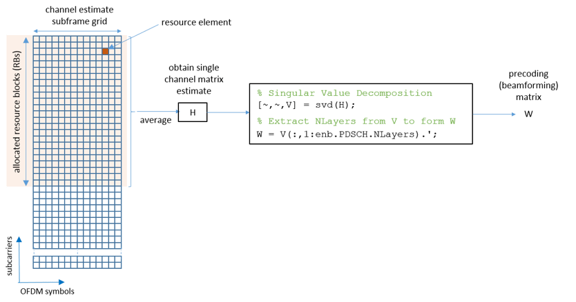
The process depicted shows how a single channel matrix estimate, H, is obtained from the whole set of allocated resource blocks by averaging over time and frequency. Using this channel estimate, H, a precoding matrix, W, is obtained via singular value decomposition.
Note that for an allocation of a single resource block, the precoding matrix W will usually be well matched to the channel conditions, with little deviation from the optimal precoding. But as the allocation size increases, the precoding matrix takes into account the average of the channel conditions over the whole allocation. This averaging causes a deviation from the optimal precoding matrix. Therefore, you can expect a degradation in performance as the size of the resource allocation increases.
Processing Loop
The 'for' loop for SNR points processing is included below. To enable the use of parallel computing for increased speed use 'parfor' instead of 'for' in the loop. This requires the Parallel Computing Toolbox. If this is not installed 'parfor' will default to the normal 'for' statement. If 'parfor' is used, it is recommended that the variable displaySimulationInformation above is set to false, otherwise the simulation information displays for each SNR point will overlap.
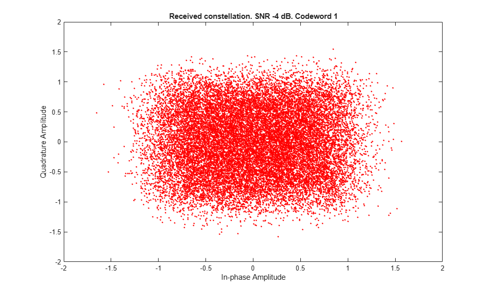
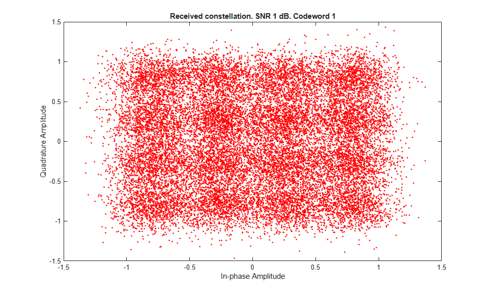
% Initialize variables used in the simulation and analysis
% Array to store the maximum throughput for all SNR points
maxThroughput = zeros(length(SNRIn),1);
% Array to store the simulation throughput for all SNR points
simThroughput = zeros(length(SNRIn),1);
% Array to store RV sequence index history
allRvSeqIdxHistory = cell(1,numel(SNRIn));
% Copy of channel structure to optimize parallel processing (only if
% running the example with Parallel Computing Toolbox)
channelInit = channel;
% During simulation some fields of enb will be updated, make a copy to
% reinitialize it when simulating each SNR point
enbInit = enb;

% For TDD precalculate vector of subframe types: D, S and U for downlink,
% special and uplink respectively
if strcmpi(DuplexMode,'TDD')
    subframeType = char(10,1);
    initialSubframeNo = enb.NSubframe;
    for sNo=0:9 % for all subframes in a frame
        enb.NSubframe = sNo;
        duplexInfo = lteDuplexingInfo(enb);
        subframeType(sNo+1) = duplexInfo.SubframeType(1); % first char: D, S or U
    end
    enb.NSubframe = initialSubframeNo;
end

% CFI can be a scalar or a vector, create a local copy of CFI as a vector
% (one value per subframe)
if numel(enb.CFI) == 1
    CFI = repmat(enb.CFI,1,10);
else
    CFI = enb.CFI;
end

% Get the HARQ ID sequence for HARQ processing. This is a list of indices
% for HARQ process scheduling.
[~,~,enbOut] = lteRMCDLTool(enb, []);
harqProcessSequenceInit = enbOut.PDSCH.HARQProcessSequence;

for snrIdx = 1:numel(SNRIn)     % comment out for parallel computing
%parfor snrIdx = 1:numel(SNRIn) % uncomment for parallel computing

    % Set the random number generator seed depending on the loop variable
    % to ensure independent random streams
    rng(snrIdx,'combRecursive');

    % Reinitialize variables (they are modified during each SNR point
    % simulation)
    enb = enbInit;
    channel = channelInit;
    harqProcessSequence = harqProcessSequenceInit;

    % Initialize the state of all HARQ processes
    harqProcesses = hNewHARQProcess(enb);

    % Set up variables for the main loop
    lastOffset = 7;       % Initialize overall frame timing offset
                          % (set equal to channel implementation delay)
    frameOffset = 7;      % Initialize frame timing offset
                          % (set equal to channel implementation delay)
    blkCRC = [];          % Block CRC for all considered subframes
    bitTput = [];         % Number of successfully received bits per subframe
    txedTrBlkSizes = [];  % Number of transmitted bits per subframe
    precodingMatrix = []; % Precoding matrix
    rxSymbols = [];       % DL-SCH symbols for constellation plot (codeword 1)
    rxSymbols2 = [];      % DL-SCH symbols for constellation plot (codeword 2)

    % The variable rvSeqIdxHistory stores the history of the value of the
    % RV index sequence for all the HARQ processes
    rvSeqIdxHistory = nan(ncw, NFrames*10);

    % Flag to indicate if a precoding matrix W is available. This is useful
    % if no W has been calculated at the beginning of the simulation.
    isWready = false;
    % Flag to indicate is a subframe is to be processed. Set to true if
    % there is data to be processed in the subframe, i.e. DL subframe or
    % non-zero transport block size.
    processSubframe = false;

    % Main for loop: for all subframes
    for subframeNo = 0:(NFrames*10-1)

        % Update subframe number
        enb.NSubframe = subframeNo;

        % Load CFI for current subframe
        enb.CFI = CFI(mod(subframeNo,length(CFI))+1);

        % Channel time for the current subframe
        channel.InitTime = subframeNo/1000;

        % Get HARQ process ID for the subframe from HARQ process sequence
        harqID = harqProcessSequence(mod(subframeNo, length(harqProcessSequence))+1);

        % Extract the current subframe transport block size(s)
        trBlk = trBlkSizes(:, mod(subframeNo, 10)+1).';

        % Load precoding matrix calculated in previous subframe if it
        % exists and if there is data to transmit. Set the flag to trigger
        % subframe processing.
        if isWready && any(trBlk)
            harqProcesses(harqID).txConfig.W = precodingMatrix;
            processSubframe = true;
        else
            processSubframe = false;
        end

        % Precoding matrix calculation
        if strcmpi(DuplexMode,'TDD')
            % Estimate channel in UL subframe
            if strcmp(subframeType(mod(subframeNo,10)+1),'U')
                processSubframe = false; % UL subframe, no DL data
                % Only perform channel estimate if next subframe is DL
                if strcmp(subframeType(mod((subframeNo+1),10)+1),'D')
                    precodingMatrix = hCalculatePrecodingMatrix(enb, channel);
                    isWready = true;
                end
            end
        else %FDD
            % Get transport block for next subframe
            trBlkNext = trBlkSizes(:, mod(subframeNo+1, 10)+1).';

            % Calculate the precoding matrix for next subframe only if it
            % carries data (i.e. non-zero trBlkNext)
            if any(trBlkNext)
                precodingMatrix = hCalculatePrecodingMatrix(enb, channel);
                isWready = true;
            else
                isWready = false;
            end
        end

        % Subframe processing
        if processSubframe

            % Update current HARQ process
            harqProcesses(harqID) = hHARQScheduling( ...
                harqProcesses(harqID), subframeNo, rvSequence);

            % Display run time information
            if displaySimulationInformation && any(trBlk)
                disp(' ');
                disp(['Subframe: ' num2str(subframeNo) '. HARQ process index: ' num2str(harqID)]);
            end

            % Update RV sequence index table
            rvSeqIdxHistory(:,subframeNo+1) = ...
                harqProcesses(harqID).txConfig.RVIdx.';

            % Update the PDSCH transmission configuration with HARQ
            % process state
            enb.PDSCH = harqProcesses(harqID).txConfig;

            % Cell payload
            dlschTransportBlk = harqProcesses(harqID).data;

            % Create transmit waveform
            txWaveform = lteRMCDLTool(enb, dlschTransportBlk);

            % Add maxChDelay sample padding. This is to cover the range of delays
            % expected from channel modeling (a combination of
            % implementation delay and channel delay spread)
            txWaveform =  [txWaveform; zeros(maxChDelay, ntxants)]; %#ok<AGROW>

            % Pass data through channel model
            rxNoiselessWaveform = lteFadingChannel(channel,txWaveform);

            % Calculate noise gain including compensation for downlink
            % power allocation
            SNR = 10^((SNRIn(snrIdx)-enb.PDSCH.Rho)/20);

            % Normalize noise power to take account of sampling rate,
            % which is a function of the IFFT size used in OFDM
            % modulation, and the number of antennas
            N0 = 1/(sqrt(2.0*ntxants*double(ofdmInfo.Nfft))*SNR);

            % Create additive white Gaussian noise
            noise = N0*complex(randn(size(rxNoiselessWaveform)),...
                randn(size(rxNoiselessWaveform)));

            % Add AWGN to the received time domain waveform and scale
            % for required power
            rxWaveform = rxNoiselessWaveform + noise;

            % Receiver
            % Once every frame, on subframe 0, calculate a new
            % synchronization offset. An offset within the range of
            % delays expected from the channel modeling (a combination
            % of implementation delay and channel delay spread)
            % indicates success
            if (mod(subframeNo,10)==0)
                frameOffset = lteDLFrameOffset(enb,rxWaveform);
                if (frameOffset > maxChDelay)
                    frameOffset = lastOffset;
                end
                lastOffset = frameOffset;
            end
            rxWaveform = rxWaveform(1+frameOffset:end,:);

            % Perform OFDM demodulation on the received data to obtain
            % the resource grid
            rxSubframe = lteOFDMDemodulate(enb,rxWaveform);

            % Channel estimation
            [estChannelGrid,noiseEst] = ...
                lteDLChannelEstimate(enb,enb.PDSCH,cec,rxSubframe);

            % Perform equalization, deprecoding, layer demapping,
            % demodulation and descrambling on the received data using the
            % channel estimate.

            % Get PDSCH indices
            pdschIndices = ltePDSCHIndices(enb,enb.PDSCH,enb.PDSCH.PRBSet);

            % Get PDSCH resource elements. Scale the received subframe
            % by the PDSCH power factor Rho. The PDSCH is scaled by
            % Rho, while the cell reference symbols used for channel
            % estimation (used in the PDSCH decoding stage) are not.
            [pdschRx, pdschHest] = lteExtractResources(pdschIndices, ...
                rxSubframe*(10^(-enb.PDSCH.Rho/20)),estChannelGrid);

            % Decode PDSCH
            [dlschBits,dlschSymbols] = ltePDSCHDecode(enb,enb.PDSCH,...
                pdschRx,pdschHest,noiseEst);

            % Store the decoded DLSCH symbols for constellation
            % plotting
            rxSymbols = [rxSymbols; dlschSymbols{1}(:)]; %#ok<AGROW>
            if ncw>1
                rxSymbols2 = [rxSymbols2; dlschSymbols{2}(:)]; %#ok<AGROW>
            end

            % Decode the DL-SCH
            [decbits,harqProcesses(harqID).blkerr,harqProcesses(harqID).decState] = ...
                lteDLSCHDecode(enb,enb.PDSCH,trBlk,dlschBits, ...
                harqProcesses(harqID).decState);

            % Display block errors
            if displaySimulationInformation
                if any(harqProcesses(harqID).blkerr)
                    disp(['Block error. RV index: ' num2str(harqProcesses(harqID).txConfig.RVIdx) ', CRC: ' num2str(harqProcesses(harqID).blkerr)])
                else
                    disp(['No error. RV index: ' num2str(harqProcesses(harqID).txConfig.RVIdx) ', CRC: ' num2str(harqProcesses(harqID).blkerr)])
                end
            end

            % Store values needed to calculate throughput
            % Only for subframes with data
            if(any(trBlk))
                blkCRC = [blkCRC harqProcesses(harqID).blkerr]; %#ok<AGROW>
                bitTput = [bitTput trBlk.*(1- ...
                    harqProcesses(harqID).blkerr)]; %#ok<AGROW>
                txedTrBlkSizes = [txedTrBlkSizes trBlk]; %#ok<AGROW>
            end
        end
    end

    % Plot received symbol constellation
    if displaySimulationInformation
        figure;plot(rxSymbols,'.r'); title(['Received constellation. SNR ' ...
                                 num2str(SNRIn(snrIdx)) ' dB. Codeword 1'])
        xlabel('In-phase Amplitude');
        ylabel('Quadrature Amplitude');
        if ncw>1
            figure;plot(rxSymbols2,'.r'); title(['Received constellation. SNR ' ...
                                 num2str(SNRIn(snrIdx)) ' dB. Codeword 2'])
            xlabel('In-phase Amplitude');
            ylabel('Quadrature Amplitude');
        end
    end

    % Calculate the maximum and simulated throughput
    maxThroughput(snrIdx) = sum(txedTrBlkSizes); % Max possible throughput
    simThroughput(snrIdx) = sum(bitTput,2);      % Simulated throughput

    % Display the results dynamically in the command window
    fprintf('\nSNR = %.2f dB. Throughput for %d Frame(s) = %.4f Mbps\n',...
         SNRIn(snrIdx),NFrames,1e-6*simThroughput(snrIdx)/(NFrames*10e-3));
    fprintf('SNR = %.2f dB. Throughput(%%) for %d Frame(s) = %.4f %%\n',...
    SNRIn(snrIdx),NFrames,simThroughput(snrIdx)*100/maxThroughput(snrIdx));

    allRvSeqIdxHistory{snrIdx} = rvSeqIdxHistory;

end
Subframe: 4. HARQ process index: 3
Block error. RV index: 1, CRC: 1

Subframe: 5. HARQ process index: 4
Block error. RV index: 1, CRC: 1

Subframe: 6. HARQ process index: 5
Block error. RV index: 1, CRC: 1

Subframe: 9. HARQ process index: 6
Block error. RV index: 1, CRC: 1

Subframe: 10. HARQ process index: 7
Block error. RV index: 1, CRC: 1

Subframe: 11. HARQ process index: 2
Block error. RV index: 1, CRC: 1

Subframe: 14. HARQ process index: 1
Block error. RV index: 1, CRC: 1

Subframe: 15. HARQ process index: 3
No error. RV index: 2, CRC: 0

Subframe: 16. HARQ process index: 5
No error. RV index: 2, CRC: 0

Subframe: 19. HARQ process index: 4
No error. RV index: 2, CRC: 0

SNR = -4.00 dB. Throughput for 2 Frame(s) = 0.6588 Mbps
SNR = -4.00 dB. Throughput(%) for 2 Frame(s) = 29.8694 %

Subframe: 4. HARQ process index: 3
No error. RV index: 1, CRC: 0

Subframe: 5. HARQ process index: 4
No error. RV index: 1, CRC: 0

Subframe: 6. HARQ process index: 5
No error. RV index: 1, CRC: 0

Subframe: 9. HARQ process index: 6
No error. RV index: 1, CRC: 0

Subframe: 10. HARQ process index: 7
No error. RV index: 1, CRC: 0

Subframe: 11. HARQ process index: 2
No error. RV index: 1, CRC: 0

Subframe: 14. HARQ process index: 1
No error. RV index: 1, CRC: 0

Subframe: 15. HARQ process index: 3
No error. RV index: 1, CRC: 0

Subframe: 16. HARQ process index: 5
No error. RV index: 1, CRC: 0

Subframe: 19. HARQ process index: 4
No error. RV index: 1, CRC: 0

SNR = 1.00 dB. Throughput for 2 Frame(s) = 2.2056 Mbps
SNR = 1.00 dB. Throughput(%) for 2 Frame(s) = 100.0000 %
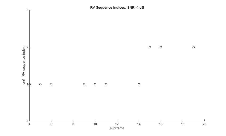
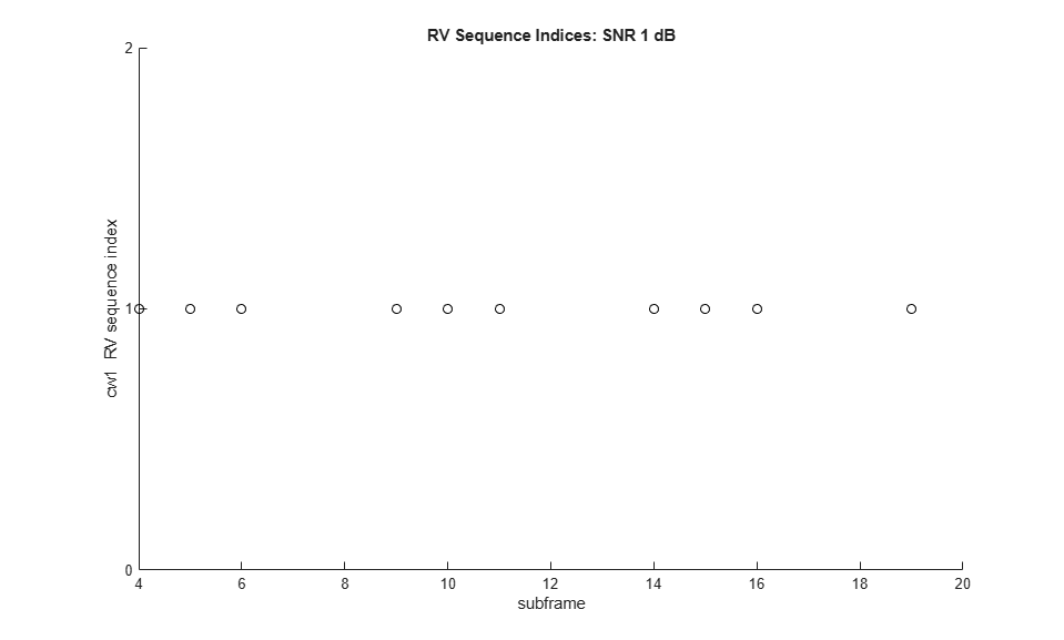
RV Sequence Index Plots
The code below generates plots with the value of the indices to the elements in the RV sequence for the simulated subframes. This provides an idea of the retransmissions required. The reason for plotting the indices instead of the RV values is that the latter may not be organized in ascending order. For example, in some cases the RV sequence can be [0, 2, 3, 1]. Plotting these values as they are used will not provide a clear idea of the number of retransmissions needed.
When transmitting a new transport block, the first element of the RV sequence is used, and a value of 1 is shown for that subframe. This is the case at the beginning of the simulation. If a retransmission is required, the next element in the RV sequence is selected and the index is increased. A value of 2 will be plotted for the subframe where the retransmission takes place. If further retransmissions are required, the index value will increase further. The plots do not show any value in subframe 5 of consecutive frames. This is because no data is transmitted in those subframes for the setup used in this example.
hPlotRVSequence(SNRIn,allRvSeqIdxHistory,NFrames);
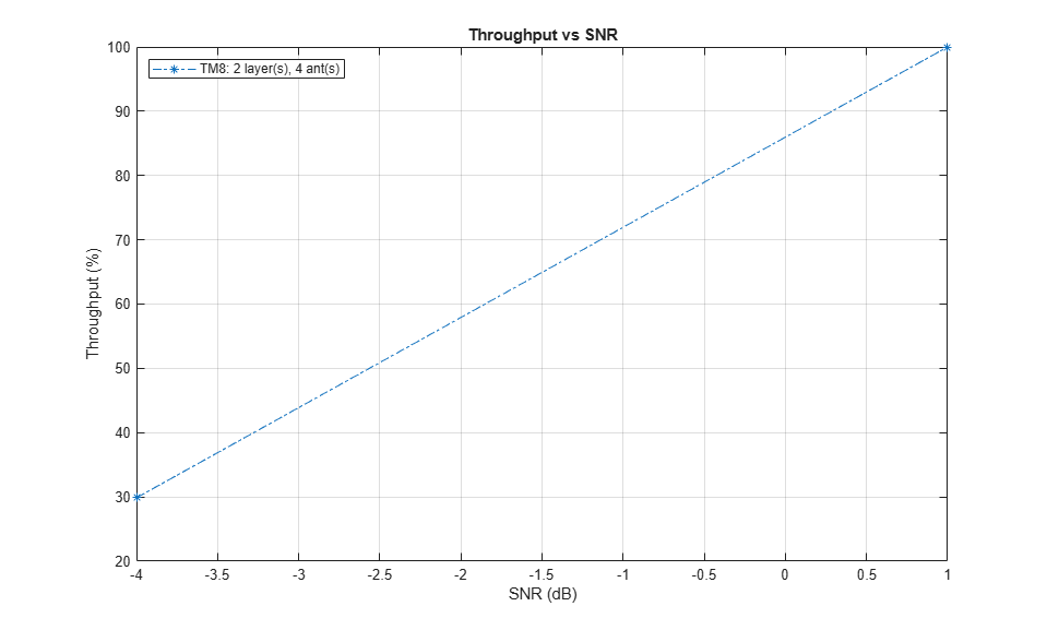
Throughput Results
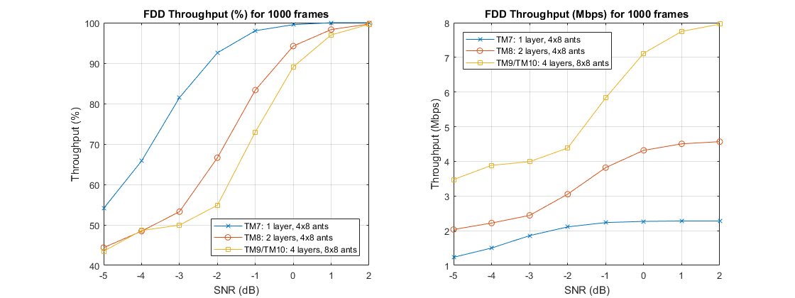
The throughput results are displayed in the MATLAB® command window after each SNR point is completed. They are also captured in output arrays simThroughput and maxThroughput. simThroughput stores the measured throughput in number of bits for all simulated SNR points. maxThroughput stores the maximum possible throughput in number of bits for each simulated SNR point.
% Plot throughput
figure
legendString = [char(txMode) ': ' num2str(simulationParameters.PDSCH.NLayers) ...
                ' layer(s), ' num2str(ntxants) ' ant(s)'];
plot(SNRIn, simThroughput*100./maxThroughput,'*-.');
xlabel('SNR (dB)');
ylabel('Throughput (%)');
title('Throughput vs SNR');
legend(legendString,'Location','NorthWest');
grid on;
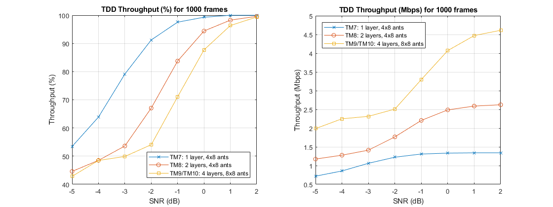
For statistically valid results, the simulation should be run for a larger number of frames. The figure below compares the throughput results for TDD and FDD when simulating 1000 frames.
Appendix
This example uses the following helper functions:
Selected Bibliography
3GPP TS 36.101 "User Equipment (UE) radio transmission and reception"