이 번역 페이지는 최신 내용을 담고 있지 않습니다. 최신 내용을 영문으로 보려면 여기를 클릭하십시오.
라이다 및 카메라 보정
이 예제에서는 3차원 라이다 센서와 카메라 간의 강체 변환을 추정한 다음 강체 변환 행렬을 사용하여 라이다 데이터와 카메라 데이터를 융합하는 방법을 보여줍니다.
전체 보기
라이다 센서는 3차원 공간 정보를 수집하는 반면 카메라는 2차원 영상에서 해당 공간의 모습과 텍스처를 캡처하기 때문에 자율주행 응용 분야에서는 일반적으로 라이다 센서와 카메라가 함께 사용됩니다. 이들 센서의 데이터를 융합하여 객체 검출과 객체 분류를 개선할 수 있습니다. 라이다-카메라 보정은 이 두 센서 간의 상대적 회전 및 평행 이동을 제공하는 변환 행렬을 추정합니다. 라이다-카메라 데이터 융합을 수행할 때 이 행렬을 사용하게 됩니다.
다음 다이어그램은 LCC(라이다 및 카메라 보정) 과정에 대한 워크플로를 보여줍니다. 여기서는 체커보드를 보정 객체로 사용하고 있습니다. 라이다 데이터와 카메라 데이터에서 체커보드 코너와 평면을 추출한 다음 이들 좌표계 간의 기하학적 관계를 설정하여 보정을 수행합니다. 라이다-카메라 보정에 대한 자세한 내용은 라이다-카메라 보정이란? 항목을 참조하십시오.

이 예제에서는 두 가지 다른 라이다 센서, 즉 HDL-64 센서와 VLP-16 센서의 데이터를 사용합니다. HDL-64 센서의 경우는 Gazebo 환경에서 수집된 데이터를 사용합니다.

HDL-64 센서는 데이터를 일련의 PNG 영상 및 대응하는 PCD 포인트 클라우드로 캡처합니다. 이 예제에서는 카메라의 내부 파라미터를 이미 알고 있는 것으로 가정합니다. 카메라의 내부 파라미터를 추출하는 방법에 대한 자세한 내용은 단일 카메라 보정의 정확도 평가하기 항목을 참조하십시오.
데이터 불러오기
Gazebo에서 Velodyne HDL-64 센서 데이터를 불러옵니다.
imagePath = fullfile(toolboxdir('lidar'),'lidardata','lcc','HDL64','images');
ptCloudPath = fullfile(toolboxdir('lidar'),'lidardata','lcc','HDL64','pointCloud');
cameraParamsPath = fullfile(imagePath,'calibration.mat');

% Load camera intrinsics.
intrinsic = load(cameraParamsPath);

% Load images using imageDatastore.
imds = imageDatastore(imagePath);
imageFileNames = imds.Files;

% Load point cloud files.
pcds = fileDatastore(ptCloudPath,'ReadFcn',@pcread);
ptCloudFileNames = pcds.Files;

% Square size of the checkerboard.
squareSize = 200;

% Set random seed to generate reproducible results.
rng('default')
체커보드 코너 검출하기
이 예제에서는 보정을 위해 체커보드 패턴을 사용합니다. 먼저, 카메라 데이터에서 체커보드 가장자리를 추정합니다. estimateCheckerboardCorners3d 함수를 사용하여 체커보드 코너의 좌표와 실제 체커보드의 크기(단위: 밀리미터)를 계산합니다. 이 함수는 코너를 세계 좌표계의 3차원 좌표로 추정합니다.
[imageCorners3d,checkerboardDimension,dataUsed] = ...
    estimateCheckerboardCorners3d(imageFileNames,intrinsic.cameraParams,squareSize);

% Remove image files that are not used.
imageFileNames = imageFileNames(dataUsed);
helperShowImageCorners 헬퍼 함수를 사용하여 결과를 시각화합니다.
% Display checkerboard corners.
helperShowImageCorners(imageCorners3d,imageFileNames,intrinsic.cameraParams)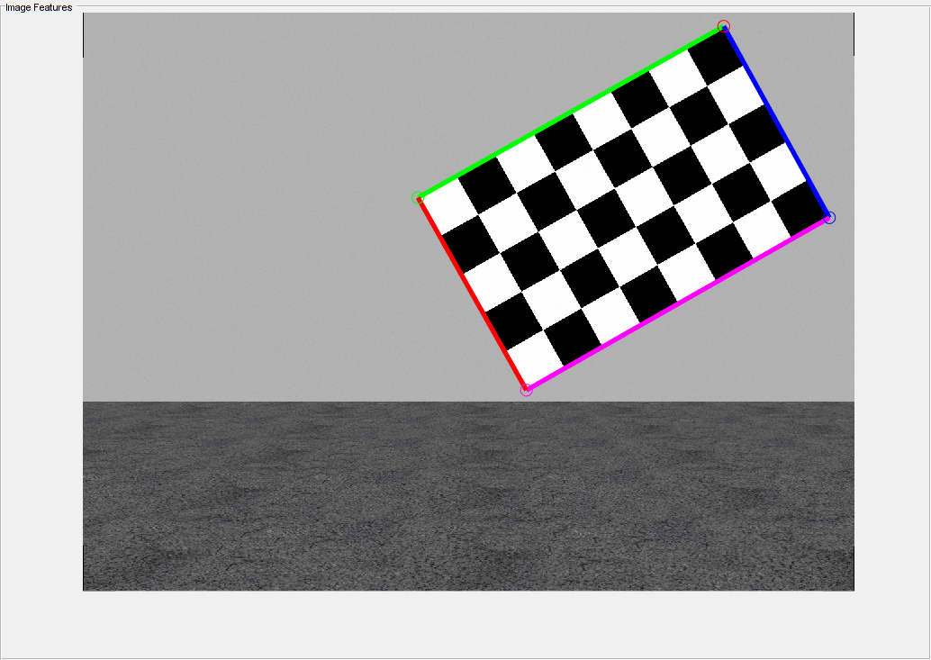
체커보드 평면 검출하기
다음으로, detectRectangularPlanePoints 함수를 사용하여 라이다 데이터에서 체커보드 평면을 검출합니다. 이 함수는 estimateCheckerboardCorners3d 함수에 의해 계산된 체커보드 크기를 사용하여 체커보드를 검출합니다.
% Extract the checkerboard ROI from the detected checkerboard image corners.
roi = helperComputeROI(imageCorners3d,5);

% Filter the point cloud files that are not used for detection.
ptCloudFileNames = ptCloudFileNames(dataUsed);
[lidarCheckerboardPlanes,framesUsed,indices] = ...
    detectRectangularPlanePoints(ptCloudFileNames,checkerboardDimension,ROI=roi);

% Remove ptCloud files that are not used.
ptCloudFileNames = ptCloudFileNames(framesUsed);

% Remove image files.
imageFileNames = imageFileNames(framesUsed);

% Remove 3-D corners from images.
imageCorners3d = imageCorners3d(:,:,framesUsed);
helperShowCheckerboardPlanes 함수를 사용하여, 검출된 체커보드를 시각화합니다.
helperShowCheckerboardPlanes(ptCloudFileNames,indices)

라이다와 카메라 보정하기
estimateLidarCameraTransform 함수를 사용하여 라이다 센서와 카메라 간의 강체 변환 행렬을 추정합니다.
[tform,errors] = estimateLidarCameraTransform(lidarCheckerboardPlanes, ...
    imageCorners3d,intrinsic.cameraParams);
보정 후에, 이 변환 행렬을 사용하여 다음을 수행할 수 있습니다.
projectLidarPointsOnImage함수를 사용하여 영상에 라이다 포인트 클라우드를 투영합니다.fuseCameraToLidar함수를 사용하여 영상의 색 정보를 통해 라이다 포인트 클라우드를 개선합니다.
helperFuseLidarCamera 함수를 사용하여, 융합된 라이다 데이터와 영상 데이터를 함께 시각화합니다.
helperFuseLidarCamera(imageFileNames,ptCloudFileNames,indices, ...
    intrinsic.cameraParams,tform);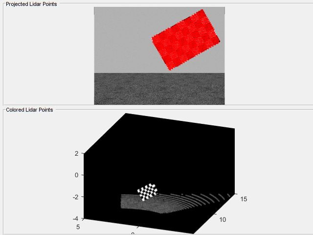
보정 오차 시각화하기
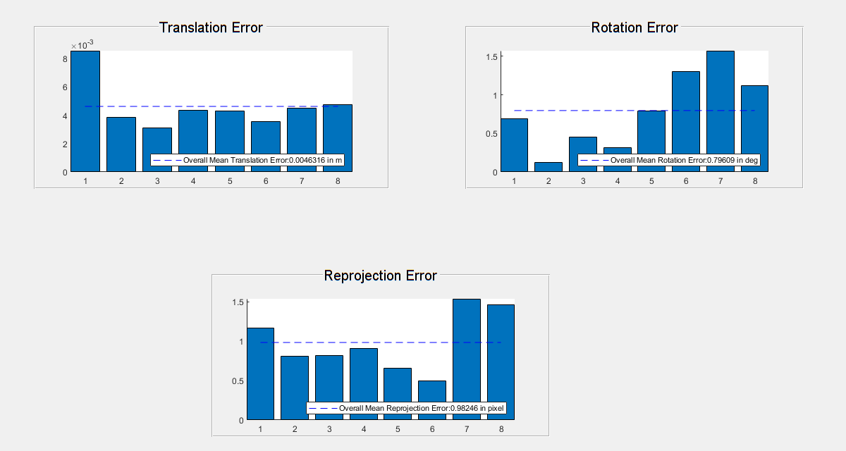
다음과 같은 유형의 오차를 사용하여 보정 정확도를 추정할 수 있습니다.
평행 이동 오차 — 포인트 클라우드에서의 체커보드 평면의 중심 좌표와 그에 대응하는 영상에서의 체커보드 평면의 중심 좌표 간의 차이입니다(단위: 미터).
회전 오차 — 포인트 클라우드에서 체커보드 평면에 의해 정의된 법선 각도와 그에 대응하는 영상에서 체커보드 평면에 의해 정의된 법선 각도 간의 차이입니다(단위: 도).
재투영 오차 — 포인트 클라우드에서의 체커보드 평면의 투영된(변환된) 중심 좌표와 그에 대응하는 영상에서의 체커보드 평면의 투영된(변환된) 중심 좌표 간의 차이입니다(단위: 픽셀).
helperShowError 함수를 사용하여, 추정된 오차 값을 플로팅합니다.
helperShowError(errors)
실제 데이터에 대한 보정
실제 VLP-16 라이다 데이터에서 LCC 워크플로를 테스트하여 성능을 평가합니다.
clear
imagePath = fullfile(toolboxdir('lidar'),'lidardata','lcc','vlp16','images');
ptCloudPath = fullfile(toolboxdir('lidar'),'lidardata','lcc','vlp16','pointCloud');
cameraParamsPath = fullfile(imagePath,'calibration.mat');

% Load camera intrinsics.
intrinsic = load(cameraParamsPath);

% Load images using imageDatastore.
imds = imageDatastore(imagePath);
imageFileNames = imds.Files;

% Load point cloud files.
pcds = fileDatastore(ptCloudPath,'ReadFcn',@pcread);
ptCloudFileNames = pcds.Files;

% Square size of the checkerboard in mm.
squareSize = 81;

% Set random seed to generate reproducible results.
rng('default')

% Extract checkerboard corners from the images.
[imageCorners3d,checkerboardDimension,dataUsed] = ...
    estimateCheckerboardCorners3d(imageFileNames,intrinsic.cameraParams,squareSize);

% Remove the unused image files.
imageFileNames = imageFileNames(dataUsed);

% Filter the point cloud files that are not used for detection.
ptCloudFileNames = ptCloudFileNames(dataUsed);

% Extract ROI from the detected checkerboard image corners.
roi = helperComputeROI(imageCorners3d,5);

% Extract checkerboard plane from point cloud data.
[lidarCheckerboardPlanes,framesUsed,indices] = detectRectangularPlanePoints( ...
    ptCloudFileNames,checkerboardDimension,RemoveGround=true,ROI=roi);
imageCorners3d = imageCorners3d(:,:,framesUsed);

% Remove ptCloud files that are not used.
ptCloudFileNames = ptCloudFileNames(framesUsed);

% Remove image files that are not used.
imageFileNames = imageFileNames(framesUsed);

[tform,errors] = estimateLidarCameraTransform(lidarCheckerboardPlanes, ...
    imageCorners3d,intrinsic.cameraParams);
helperFuseLidarCamera(imageFileNames,ptCloudFileNames,indices, ...
    intrinsic.cameraParams,tform);

% Plot the estimated error values.
helperShowError(errors);
요약
이 예제에서는 라이다-카메라 보정 워크플로에 대해 간략하게 설명하고 강체 변환 행렬을 사용하여 라이다 데이터와 카메라 데이터를 융합하는 방법을 보여줍니다.
참고 문헌
[1] Zhou, Lipu, Zimo Li, and Michael Kaess. “Automatic Extrinsic Calibration of a Camera and a 3D LiDAR Using Line and Plane Correspondences.” In 2018 IEEE/RSJ International Conference on Intelligent Robots and Systems (IROS), 5562–69. Madrid: IEEE, 2018. https://doi.org/10.1109/IROS.2018.8593660.
[2] Arun, K. S., T. S. Huang, and S. D. Blostein. “Least-Squares Fitting of Two 3-D Point Sets.” IEEE Transactions on Pattern Analysis and Machine Intelligence PAMI-9, no. 5 (September 1987): 698–700. https://doi.org/10.1109/TPAMI.1987.4767965.