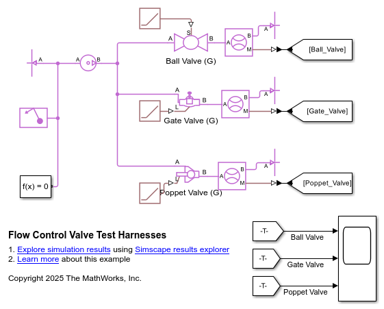
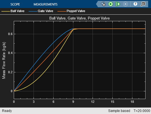
Ball Valve (G)
Libraries:
Simscape /
Fluids /
Gas /
Valves & Orifices /
Flow Control Valves
Description
The Ball Valve (G) block models flow through a ball valve in a gas network. A rotating ball with a central hole, or bore, controls the flow of the valve. When the bore aligns with the valve inlet and outlet the valve is open. The physical signal at port S controls the ball rotation.
Valve Parameterizations
The block behavior depends on the Valve parametrization parameter:
Cv flow coefficient— The flow coefficient Cv determines the block parameterization. The flow coefficient measures the ease with which a gas flows when driven by a certain pressure differential.Kv flow coefficient— The flow coefficient Kv, where , determines the block parameterization. The flow coefficient measures the ease with which a gas flows when driven by a certain pressure differential.Sonic conductance— The sonic conductance of the resistive element at steady state determines the block parameterization. The sonic conductance measures the ease with which a gas flows when choked, which is a condition in which the flow velocity is at the local speed of sound. Choking occurs when the ratio between downstream and upstream pressures reaches a critical value known as the critical pressure ratio.Orifice area— The size of the flow restriction determines the block parametrization.
Opening Area
The block calculates the ball valve opening during simulation from the input at port S. The opening area calculations depend on the Opening Characteristic parameter.
If you set Opening Characteristic to Area of overlapping
circles, the block calculates the opening area of the valve by
assuming that the valve port and the ball bore are overlapping circles. The open
area saturates when the input signal from port S goes
outside the range of 0 rad to π/2 rad.
The block calculates the opening area as
where:
Rport and Rbore are the radii of the valve port and the ball bore, respectively.
l is the displacement of the bore center from the valve port center.
φ is the rotation of the ball valve given by the physical signal S. The valve is fully shut at 0 rad and fully open at π/2 rad.
If you set Opening Characteristic to
Tabulated, the block interpolates the valve
opening from the Area vector, Cv flow coefficient
vector, Kv flow coefficient vector, or
Sonic conductance vector parameters. The elements in
these vectors correspond one-to-one to the elements in the Ball
rotation vector parameter. The block interpolates between the
data points with linear interpolation and uses nearest extrapolation for points
beyond the table boundaries.
Momentum Balance
The block equations depend on the Valve parametrization
parameter. When you set Valve parametrization to
Cv flow coefficient, the mass flow rate, , is
where:
Cv is the value of the Maximum Cv flow coefficient parameter.
Sopen is the valve opening area.
SMax is the maximum valve area when the valve is fully open.
N6 is a constant equal to 27.3 for mass flow rate in kg/hr, pressure in bar, and density in kg/m3.
Y is the expansion factor.
pin is the inlet pressure.
pout is the outlet pressure.
ρin is the inlet density.
The expansion factor is
where:
Fγ is the ratio of the isentropic exponent to 1.4.
xT is the value of the xT pressure differential ratio factor at choked flow parameter.
The block smoothly transitions to a linearized form of the equation when the pressure ratio, , rises above the value of the Laminar flow pressure ratio parameter, Blam,
where:
When the pressure ratio, , falls below , the orifice becomes choked and the block switches to the equation
When you set Valve parametrization to Kv
flow coefficient, the block uses these same equations, but
replaces Cv with
Kv by using the relation . For more information on the mass flow equations when the
Valve parametrization parameter is Kv flow
coefficient or Cv flow coefficient,
[2][3].
When you set Valve parametrization to Sonic
conductance, the mass flow rate, , is
where:
C is the value of the Maximum sonic conductance parameter.
Bcrit is the critical pressure ratio.
m is the value of the Subsonic index parameter.
Tref is the value of the ISO reference temperature parameter.
ρref is the value of the ISO reference density parameter.
Tin is the inlet temperature.
The block smoothly transitions to a linearized form of the equation when the pressure ratio, , rises above the value of the Laminar flow pressure ratio parameter Blam,
When the pressure ratio, , falls below the critical pressure ratio, Bcrit, the orifice becomes choked and the block switches to the equation
The Sonic conductance setting of the
Valve parameterization parameter is for pneumatic
applications. If you use this setting for gases other than air, you may need to
scale the sonic conductance by the square root of the specific gravity.
For more information on the mass flow equations when the Valve
parametrization parameter is Sonic
conductance, see [1].
When you set Valve parametrization to
Orifice area based on
					geometry
, the mass flow
rate, , is
where:
Sopen is the valve opening area.
S is the value of the Cross-sectional area at ports A and B parameter.
Cd is the value of the Discharge coefficient parameter.
γ is the isentropic exponent.
The block smoothly transitions to a linearized form of the equation when the pressure ratio, , rises above the value of the Laminar flow pressure ratio parameter, Blam,
When the pressure ratio, , falls below , the orifice becomes choked and the block switches to the equation
For more information on the mass flow equations when the Valve
parametrization parameter is Orifice area based on
geometry, see [4].
Mass Balance
The block assumes the volume and mass of fluid inside the valve is very small and ignores these values. As a result, no amount of fluid can accumulate in the valve. By the principle of conservation of mass, the mass flow rate into the valve through one port equals that out of the valve through the other port
where is defined as the mass flow rate into the valve through the port indicated by the A or B subscript.
Energy Balance
The resistive element of the block is an adiabatic component. No heat exchange can occur between the fluid and the wall that surrounds it. No work is done on or by the fluid as it traverses from inlet to outlet. Energy can flow only by advection, through ports A and B. By the principle of conservation of energy, the sum of the port energy flows is always equal to zero
where ϕ is the energy flow rate into the valve through ports A or B.
Assumptions and Limitations
The equation for the
Orifice area based on
								geometry
parameterization is less accurate for gases that are far from ideal.This block does not model supersonic flow.
Examples
Ports
Input
Conserving
Parameters
References
[1] ISO 6358-3, "Pneumatic fluid power – Determination of flow-rate characteristics of components using compressible fluids – Part 3: Method for calculating steady-state flow rate characteristics of systems", 2014.
[2] IEC 60534-2-3, “Industrial-process control valves – Part 2-3: Flow capacity – Test procedures”, 2015.
[3] ANSI/ISA-75.01.01, “Industrial-Process Control Valves – Part 2-1: Flow capacity – Sizing equations for fluid flow underinstalled conditions”, 2012.
[4] P. Beater, Pneumatic Drives, Springer-Verlag Berlin Heidelberg, 2007.


