Integrate SystemVerilog DPI into UVM Framework Workflow
This example shows how to generate reusable verification components from a Simulink® model as SystemVerilog DPI components using HDL Verifier™ software. You use the MATLAB-to-UVMF (mtlb2uvmf) workflow to create Universal Verification Methodology (UVM) testbenches quickly. For more information on mtlb2uvmf workflow, see MathWorks Integration from Siemens Verification Academy.
RTL designs are growing tremendously in size and complexity. Generating robust and reusable testbenches is imperative to validating complex designs and finding bugs early. Manually writing UVM-based verification testbenches and verification IPs requires enormous effort. Design verification engineers save time and effort by automating the generation of verification components and testbenches. This example shows the step-by-step process to generate fully functional UVMF testbenches and the process to reuse the block-level verification environments in generating the chip-level verification testbench.
Introduction to mtlb2uvmf Workflow
The UVM framework (UVMF) is an open-source package released by Siemens®. The package provides a code generator to generate infrastructure for the UVM-based verification testbenches. For more information, see the documentation shipped with the UVMF installation. You can download the UVMF 2023.4_2 release from Siemens Verification Academy on your Linux® machine.
This figure illustrates the mtlb2uvmf workflow.

To generate UVMF code using mtlb2uvmf workflow, follow these steps:
Generate the SystemVerilog DPI components for the MATLAB® or Simulink design and stimulus components.
Use your own RTL code for your design. Alternatively, generate the HDL code for the design component using MATLAB or Simulink HDL code generation, which requires an HDL Coder™ license.
Pass the generated folders as arguments to the
mtlb2uvmfCSH script to generate the UVMF code. These folders contain the SystemVerilog DPI components.Update the generated setup script with all the required environment variables to compile the generated DPI code correctly and link the UVMF testbench with the RTL design.
The mtlb2uvmf workflow supports these capabilities:
Generate YAML scripts by fetching all the required information from the generated DPI code to avoid manually authoring those scripts.
Integrate the DPI code into the sequences and predictor component of the generated UVMF code to avoid manually editing those files.
Model Overview
This figure shows the Simulink model you use in this example.

Save the example working folder to the exampleWorkingFolder variable and open the Simulink model.
exampleWorkingFolder = pwd;
open_system("PulseGen_Chip")
The name of the chip is PulseGen_Chip. The chip contains four submodules. The IO interface has these inputs:
bypass — Option to bypass the input signal to the
data_outoutput signal. Ifbypassis1, the chip bypasses thedata1input signal to thedata_outoutput signal. Ifbypassis2, the chip bypasses thedata2input signal to thedata_outoutput signal. Ifbypassis0, the chip returns a pulse signal based on thedata1anddata2inputs.data1 — Input data to the chip.
data2 — Input data to the chip.
valid — Valid signal corresponding to the input data signals.
The interface has these outputs:
data_out — Output data from the chip. If
bypassis0, this equation gives the output value: .valid_out — Valid signal corresponding to the output data signal.
Simulate the model.
open_system("PulseGen_Chip/scope_chip")
sim("PulseGen_Chip");
This figure shows the simulation outputs of the chip.

When bypass is 2, the data_out signal is same as the data2 signal. When bypass is 0, the data_out signal resembles a pulse signal corresponding to the data1 and data2 inputs.
This figure shows how to generate the block-level and chip-level verification testbenches using mtlb2uvmf workflow.

Block-Level Verification
This figure illustrates the architecture of block-level UVMF verification environments.

The AbsVal_Blk and PulseOut_Blk blocks are the RTL designs under test, which correspond to the subsystems in the PulseGen_Chip Simulink model. Assume that a single input interface bundles all the input signals and a single output interface bundles all the output signals. The corresponding block-level verification environments have these components:
Block_input_agent — Active agent that drives the test vectors into the input interface of the design. You can configure the internal of the agents through YAML scripts. For example, if you set the
has_coverageflag to true in the YAML script, the UVMF code generator instantiates the coverage collector component in the agent. This agent uses the DPI code for the stimulus subsystem as sequences.Block_predictor — Component that uses the DPI code generated from the design subsystem to predict the outputs. This component sends the predicted outputs to the Scoreboard component.
Block_output_agent — Passive agent that monitors the output interface of the design and transfers the signal information to the Scoreboard component.
Scoreboard — Component that compares the actual and expected design outputs received from the output agent and predictor, respectively. This component generates a uvm_error if it detects a comparison mismatch.
Block-Level Verification Environment Generation
Generate a stimulus subsystem corresponding to each of the blocks within the chip for block-level validation. This figure illustrates the stimulus subsystem for the AbsVal_Blk block in PulseGen_Chip.

open_system("PulseGen_Chip/AbsVal_Stim")To generate the block-level verification environments for all the subsystems in the chip, follow these steps.
Configure Simulink Model with Required DPI Configuration Settings
Configure the Simulink model settings to generate the required DPI code as expected by the mtlb2uvmf workflow. Use the helperConfigureModelForUVMF function to configure all the required model settings.
helperConfigureModelForUVMF("PulseGen_Chip")Alternatively, you can configure the settings manually under Model Settings.
First, in the Code Generation pane, perform these steps:
At System target file, under Target Selection, click Browse. Select
systemverilog_dpi_grt.tlcfrom the list.Set Toolchain to
Automatically locate an installed toolchain.
Next, select Code Generation > SystemVerilog DPI in the left pane.
Generate a testbench by selecting Generate test bench.
In the SystemVerilog Ports section, set Ports data types to
Bit Vector.In the same section, set Connection to
Port list.

Generate DPI Component for Stimulus and Design Subsystems
To generate the DPI components for the stimulus and design subsystems in the same folder, see step 5 in Step 5. Generate SystemVerilog DPI Component. This figure shows the generated folders after you generate the DPI components for both subsystems.

To generate the DPI components for all the blocks in PulseGen_Chip, use the helperGenerateDPIForSubsystems function.
helperGenerateDPIForSubsystems("PulseGen_Chip/AbsVal_Blk","PulseGen_Chip/AbsVal_Stim");
Generate the DPI components for the rest of the blocks.
helperGenerateDPIForSubsystems("PulseGen_Chip/SignalCompare_Blk","PulseGen_Chip/SignalCompare_Stim");
helperGenerateDPIForSubsystems("PulseGen_Chip/ValidOut_Blk","PulseGen_Chip/ValidOut_Stim");
helperGenerateDPIForSubsystems("PulseGen_Chip/PulseOut_Blk","PulseGen_Chip/PulseOut_Stim");
Generate HDL Code for Design Subsystems
The AbsVal_Blk, PulseOut_Blk, SignalCompare_Blk, and ValidOut_Blk V files correspond to the HDL code for each of the design subsystems. Alternatively, if you have an HDL Coder license, you can generate the HDL code from the design subsystems using these steps.
Under Model Settings, in the HDL Code Generation pane, set Language to
VHDLorVerilog.Select HDL Code Generation > Global Settings in the left pane. In the Clock settings section, set Reset asserted level to
Active-lowand Reset input port torst.In the Additional settings section, under Ports, select Minimize clock enables. This setting ensures that the software does not add the clock enable port to the port list in the generated HDL code.

Right-click the design subsystem. To add the HDL Coder app options to the menu, point to Select Apps and click the HDL Coder button ![]() . Then, in the HDL Coder app section, select Generate HDL Code for a Subsystem
. Then, in the HDL Coder app section, select Generate HDL Code for a Subsystem ![]() . This figure shows the generated folder after you generate the HDL code.
. This figure shows the generated folder after you generate the HDL code.

Generate UVMF Code
Set these environment variables:
UVMF_HOME– Set this environment variable to the UVMF 2023.4_2 installation path.MTI_VCO_MODE– Set this environment variable to64to use the 64-bit Questa™ executable for UVMF testbench simulations. Other simulators must be compatible but the workflow is not shown in this example.
setenv("UVMF_HOME","/home/Documents/UVMF_2023.4_2")
setenv("MTI_VCO_MODE","64")
Use the helperGenerateUVMFTestBench function to generate the UVMF testbenches for all the blocks. Pass the names of the folder that contain DPI components as inputs to this function. You must pass the folder names without the _build suffix because the mtlb2uvmf CSH script expects the folder name to be in the format <name>_build where <name> is the value you pass as an input to the mtlb2uvmf CSH script.
helperGenerateUVMFTestBench("AbsVal_Blk","AbsVal_Stim")
Generate UVMF testbench code for the other blocks.
helperGenerateUVMFTestBench("PulseOut_Blk","PulseOut_Stim")
helperGenerateUVMFTestBench("SignalCompare_Blk","SignalCompare_Stim")
helperGenerateUVMFTestBench("ValidOut_Blk","ValidOut_Stim")
Alternatively, generate the block-level UVMF testbenches manually by following these steps:
Navigate to the folder that contains the DPI artifacts for the stimulus and design subsystems.
Execute
mtlb2uvmfCSHscript with two arguments. These arguments correspond to the names of the folders that contain DPI components.Run this command in the command window on your host machine:
$UVMF_HOME/scripts/mtlb2uvmf.csh AbsVal_Blk AbsVal_Stim.
This figure illustrates the generated folder and YAML script after you generate the block-level UVMF testbenches.

Set Environment Variables in Generated Setup Script
Find the setup_AbsVal_Blk_environment_variables script with .source extension in the uvmf_template_output/project_benches/AbsVal_Blk/sim folder. This figure illustrates the contents of the generated setup file.

The script contains these environment variables:
AbsVal_Blk_VERILOG_DUT_SRC — Path to the design RTL file,
AbsVal_Blk.AbsVal_Blk_ENV_DPI_SRC — Path to the folder that contains the generated DPI files for the design.
AbsVal_Blk_ENV_GCC_COMP_ARGUMENTS — Compilation flags required to compile the DPI files for the design.
AbsVal_Blk_input_agent_IF_DPI_SRC — Path to the folder that contains the generated DPI files for the stimulus.
AbsVal_Blk_input_agent_IF_GCC_COMP_ARGUMENTS — Compilation flags required to compile the DPI files for the stimulus.
Update the environment variables by using the helperUpdateEnvironmentVariables function. The function also sets the environment variables from MATLAB.
helperUpdateEnvironmentVariables("AbsVal_Blk_Env");Update the setup scripts for UVMF testbenches of the other blocks.
helperUpdateEnvironmentVariables("PulseOut_Blk_Env");
helperUpdateEnvironmentVariables("SignalCompare_Blk_Env");
helperUpdateEnvironmentVariables("ValidOut_Blk_Env");
Alternatively, fetch the required compilation flags manually by following these steps. You can also follow these steps to fetch the compilation flags for the stimulus DPI.
Navigate to the folder that has the generated DPI files for the design. That folder contains a makefile with the name
AbsVal_Blk.Build the
infotarget in the makefile using the commandmake -f BlockA_DUT.mk info. The software prints the compilation flags to the command window of your host machine.Copy all the flags for the
CPPFLAGSvariable and paste them into the setup script to set the corresponding environment variable. Paste these flags in inverted commas, for example,setenv ENV_VARIABLE_NAME "<flags_copied_from_terminal>". This figure illustrates an example output highlighting the flags you need to copy.Execute the setup script in the command window of your host machine using the command
source setup_AbsVal_Blk_environment_variables.source.

Validate Block Functionality Using Block-Level Simulations
Execute the block-level simulations in Questa software by following these steps.
Navigate to the uvmf_template_output/project_benches/AbsVal_Blk/sim folder.
cd(fullfile("AbsVal_Blk_Env","uvmf_template_output","project_benches","AbsVal_Blk","sim"))
Execute this command in the MATLAB to run the UVMF testbench simulation in Questa.
!make debug TEST_NAME=DPI_stimgen_testIn the Questa window, enter run -all in the Transcript window. This figure shows the simulation results in Questa.

Navigate back to the example working folder.
cd(exampleWorkingFolder);
Chip-Level Verification
This figure illustrates the chip-level verification environment.

The chip-level environment instantiates all the block-level verification environments. The input and output interfaces of the blocks in the chip are connected to the input and output agents in their corresponding block-level environments. You need to configure all the agents in the block-level environments to be passive because they must not drive the signals into their corresponding block interfaces. Instantiate a chip-level input agent in chipEnv, which drives the test vectors into the chip input interface. This agent uses the generated DPI code for the chip-level stimulus subsystem.
This architecture reuses all the block-level environments to run the chip-level verification simulations by requiring an additional DPI code generation for the chip-level stimulus. The scoreboard mismatches in the corresponding block-level environments indicate the flaws in the design. Reusing the block-level verification environments helps to scope down the issue in chip-level simulation failures.
Chip-Level Verification Environment Generation
Use the PulseGen_Stim subsystem in the PulseGen_Chip model as the stimulus for the chip.
open_system("PulseGen_Chip/PulseGen_Stim")Generate DPI Component for Stimulus Subsystem
Generate the DPI component for the chip-level stimulus subsystem. In this case, you need not generate the DPI component for the chip subsystem because the chip-level environment reuses the block-level DPI components. Generate the DPI component for PulseGen_Chip using the helperGenerateDPIForSubsystems function.
helperGenerateDPIForSubsystems("PulseGen_Chip/PulseGen_Stim");Generate Top-Level Verilog Module
Use the PulseGen_Chip file as the top-level Verilog module. Alternatively, you can manually write a top level Verilog file instantiating all the submodules with appropriate connections between them. This figure illustrates a part of the chip-level HDL code, which has instantiations of the block-level modules.

You also need to include all the block-level HDL files in this top-level module. This figure shows how to include the block-level HDL files.

Write YAML Script Describing Chip-Level Environment
YAML scripts are the only way to convey the information about your UVMF testbench architecture to the UVMF code generator. You need to author a YAML script to generate the UVMF code for the chip-level verification according to the architecture described in the previous section. The YAML script must contain this information:
Block-level environment instantiations in the chip-level environment.
All the agents in the block-level environments must be configured as
PASSIVE.Chip-level input agent instantiation in the chip-level environment and the definition of DPI interface for this agent. For more information, see the Interface YAML Structure chapter of the UVMF_Code_Generator_YAML_Reference document shipped with your UVMF installation.
Instead of authoring your own script, you can use the Chip YAML script for this example.
open("Chip.yaml")Generate UVMF Code
To provide all the block-level YAML files and the YAML script describing the chip-level environment to UVMF code generator, follow these steps:
1. Copy all the YAML files to a single folder.
copyfile("AbsVal_Blk_Env/output_mtlb.yaml","PulseGen_Chip_Env/AbsVal_Blk.yaml",'f');
copyfile("SignalCompare_Blk_Env/output_mtlb.yaml","PulseGen_Chip_Env/SignalCompare_Blk.yaml",'f');
copyfile("ValidOut_Blk_Env/output_mtlb.yaml","PulseGen_Chip_Env/ValidOut_Blk.yaml",'f');
copyfile("PulseOut_Blk_Env/output_mtlb.yaml","PulseGen_Chip_Env/PulseOut_Blk.yaml",'f');
copyfile("Chip.yaml","PulseGen_Chip_Env/Chip.yaml",'f');
2. Navigate to the PulseGen_Chip_Env folder.
cd("PulseGen_Chip_Env")3. Execute the yaml2uvmf command by providing the YAML file names as arguments to the yaml2uvmf script.
!$UVMF_HOME/scripts/yaml2uvmf.py AbsVal_Blk.yaml SignalCompare_Blk.yaml ValidOut_Blk.yaml PulseOut_Blk.yaml Chip.yamlThis figure shows the generated folder and YAML script.

Navigate back to the example working folder.
cd(exampleWorkingFolder);
Set Environment Variables in Generated Setup Script
Because the chip subsystem does not have a separate DPI component, you need to set only these environment variables:
PulseGen_Chip_VERILOG_DUT_SRCPulseGen_Chip_input_agent_IF_DPI_SRCPulseGen_Chip_input_agent_IF_GCC_COMP_ARGUMENTS
Update the setup file for the chip-level environment by using the helperUpdateEnvironmentVariables function.
helperUpdateEnvironmentVariables("PulseGen_Chip_Env")Update Generated hdl_top SystemVerilog File
To ensure that all the mtlb2uvmf flow files are in the correct folders, execute the scripts with the .sh extension whose names take the form <NAME>_mtlb_prep. For the block-level environments, the mtlb2uvmf script executes these files. However, for the chip-level environment, you need to manually execute these files because you do not use mtlb2uvmf script in this case. Use the helperExecuteMtlbScripts function to automate this process. Pass the path to the uvmf_template_out folder as an input to the helperExecuteMtlbScripts function.
helperExecuteMtlbScripts(fullfile("PulseGen_Chip_Env","uvmf_template_output"))
The hdl_top SV file is the top-level module that instantiates all the synthesizable content. This file is in the uvmf_template_output/project_benches/PulseGen_Chip/tb/testbench folder. By default, this file assumes that all the interfaces are in the top-level DUT. Consequently, the file references all the IO signals of the blocks as DUT.<BLOCK_INTERFACE_NAME>.<IO_SIGNAL_NAME>. However, the block-level interfaces are in the block instantiations in the chip, so you must reference the IO signals in this format:
DUT.<BLOCK_INSTANCE_NAME>.<BLOCK_INTERFACE_NAME>.<IO_SIGNAL_NAME>
Modify the hdl_top SV file to reflect these changes. This figure shows one of these differences in the generated hdl_top SV file and the modified file.

You can compare the attached hdl_top SV file with the generated hdl_top SV file to understand all the differences. Open the hdl_top SV file.
open("hdl_top.sv")Replace the generated hdl_top SV file with this updated hdl_top SV file.
copyfile("hdl_top.sv",fullfile("PulseGen_Chip_Env","uvmf_template_output","project_benches","PulseGen_Chip","tb","testbench","hdl_top.sv"),'f')
Validate Chip Functionality Using Chip-Level Simulations
Follow the process mentioned in Step 6 of generating block-level verification environments to perform a chip-level simulation.
cd(fullfile("PulseGen_Chip_Env","uvmf_template_output","project_benches","PulseGen_Chip","sim"))
Execute the UVMF testbench simulation in Questa.
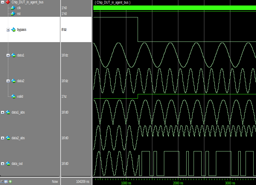
!make debug TEST_NAME=DPI_stimgen_testYou can add the data_out signal and other signals of interest to the wave window in Questa before you start the simulation. After you add the signals, enter run -all in the Transcript window of Questa to start the simulation. This figure shows the chip-level simulation results in Questa software.
Navigate back to the example working folder.
cd(exampleWorkingFolder);
Conclusion
This example shows how to generate SystemVerilog DPI components from Simulink and integrate into UVMF using mtlb2uvmf workflow. The example lays out a step-by-step process to generate the chip-level verification environment by reusing the block-level UVMF environments. You can follow this approach to generate the UVMF environments for your designs.