Floating-Point to Fixed-Point Conversion
R2026bThis example shows how to convert a floating-point MATLAB® design to a fixed-point implementation by using the HDL Workflow Advisor.
Signal processing applications for reconfigurable platforms require algorithms that are typically specified using floating-point operations. However, for power, cost, and performance reasons, they are usually implemented with fixed-point operations either in software for DSP cores or as special-purpose hardware in FPGAs. Fixed-point conversion can be very challenging and time-consuming, typically demanding 25 to 50 percent of the total design and implementation time. Automated tools can simplify and accelerate the conversion process.
For software implementations, the aim is to define an optimized fixed-point specification that minimizes the code size and the execution time for a given computation accuracy constraint. This optimization is achieved through the modification of the binary point location (for scaling) and the selection of the data word length according to the different data types supported by the target processor.
For hardware implementations, the complete architecture can be optimized. An efficient implementation minimizes both the area used and the power consumption. Thus, the conversion process typically focuses on minimizing the operator word length.
The automated floating-point to fixed-point workflow is integrated into the HDL Workflow Advisor. For more information, see Generate HDL Code from MATLAB Algorithms.
Introduction
The floating-point to fixed-point conversion workflow in HDL Coder™ includes the following steps:
Verify that the floating-point design is compatible with code generation.
Compute fixed-point types based on the simulation of the test bench.
Generate readable and traceable fixed-point MATLAB code by applying proposed types.
Verify the generated fixed-point design.
Compare the numerical accuracy of the generated fixed-point code with the original floating-point code.
MATLAB Design
The MATLAB design is a second-order direct-form 2 transposed filter. This example also contains a MATLAB test bench that exercises the filter.
design_name = "mlhdlc_df2t_filter";
testbench_name = "mlhdlc_df2t_filter_tb";
Examine the MATLAB design.
evalc('open(design_name)');
For the floating-point to fixed-point workflow, use a complete test bench. The quality of the proposed fixed-point data types depends on how well the test bench covers the dynamic range of the design with the desired accuracy.
For details on requirements for the floating-point design and the test bench, see the Floating-Point Design Structure section of Working with Generated Fixed-Point Files.
evalc('open(testbench_name)');
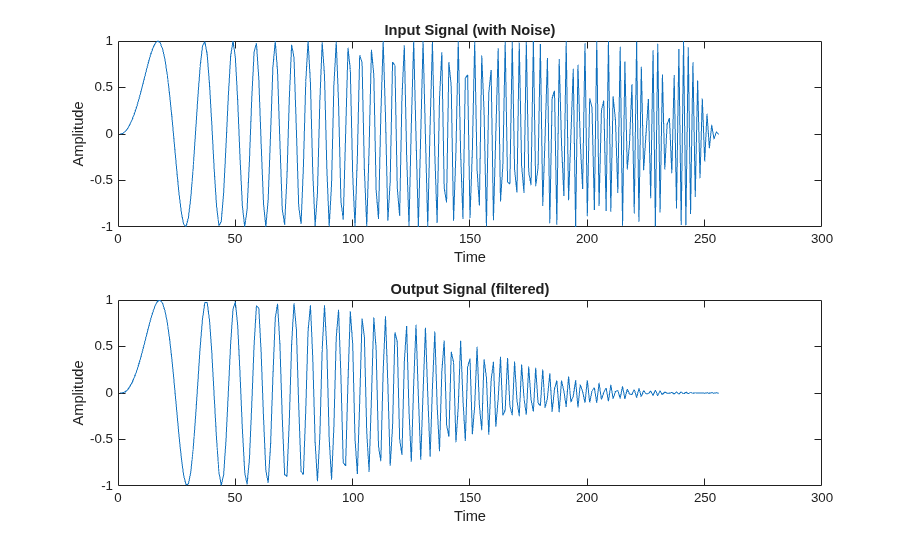
Simulate the Design
Simulate the design with the test bench before code generation to make sure there are no runtime errors.
mlhdlc_df2t_filter_tb
Create an HDL Coder Project
To create a new project and open the HDL Workflow Advisor, enter this command in the MATLAB Command Window:
coder -hdlcoder -new flt2fix_project
Next, in the Define Input Types task, add the file mlhdlc_filter.m to the project as the MATLAB Function and the file mlhdlc_filter_tb.m as the MATLAB Test Bench.
For a more complete tutorial on creating and populating MATLAB HDL Coder projects, see Generate HDL Code from MATLAB Algorithms.
Fixed-Point Code Generation Workflow
The floating-point to fixed-point conversion workflow allows you to:
Verify that the floating-point design is code generation compliant
Propose fixed-point types based on simulation data and word length settings
Manually adjust the proposed fixed-point types
Validate the proposed fixed-point types
Verify that the generated fixed-point MATLAB code has the desired numeric accuracy
Step 1: Define Input Types
In this task, the HDL Workflow Advisor infers the input types automatically by executing the MATLAB test bench.
Click Run to execute this step. The app runs the test bench and determines the input variable x as scalar double, double(1x1).
Step 2: Build Instrumented MEX Function
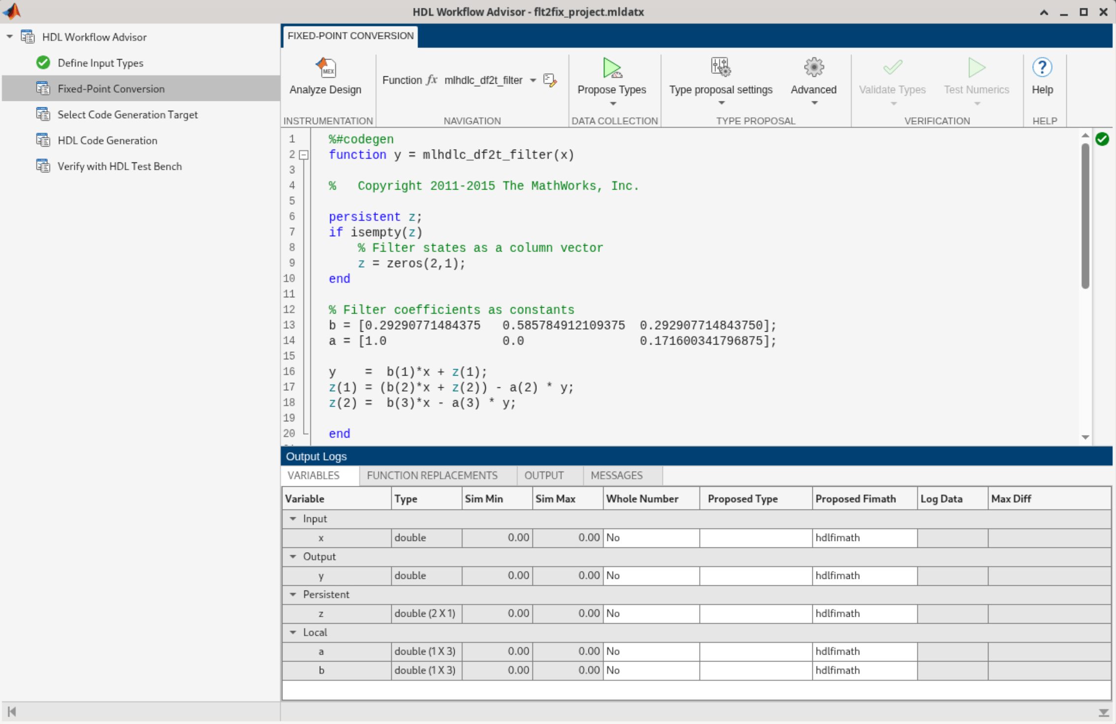
In the Fixed-Point Conversion task, click Analyze Design. The app generates an instrumented MEX function for data type range analysis.
The app builds the design with the input types defined in the Define Input Types task. After the build is successful in the Variables tab, in the Type column, the app shows the inferred types for all variables in the design.
Step 3: Perform Range Analysis
Next, click Propose Types to perform a range analysis. The app runs a simulation with the test bench and displays simulation minimum and maximum ranges in the Variables tab in the Sim Min and Sim Max columns.
The app proposes fixed-point types based on the simulated ranges and the fimath settings.
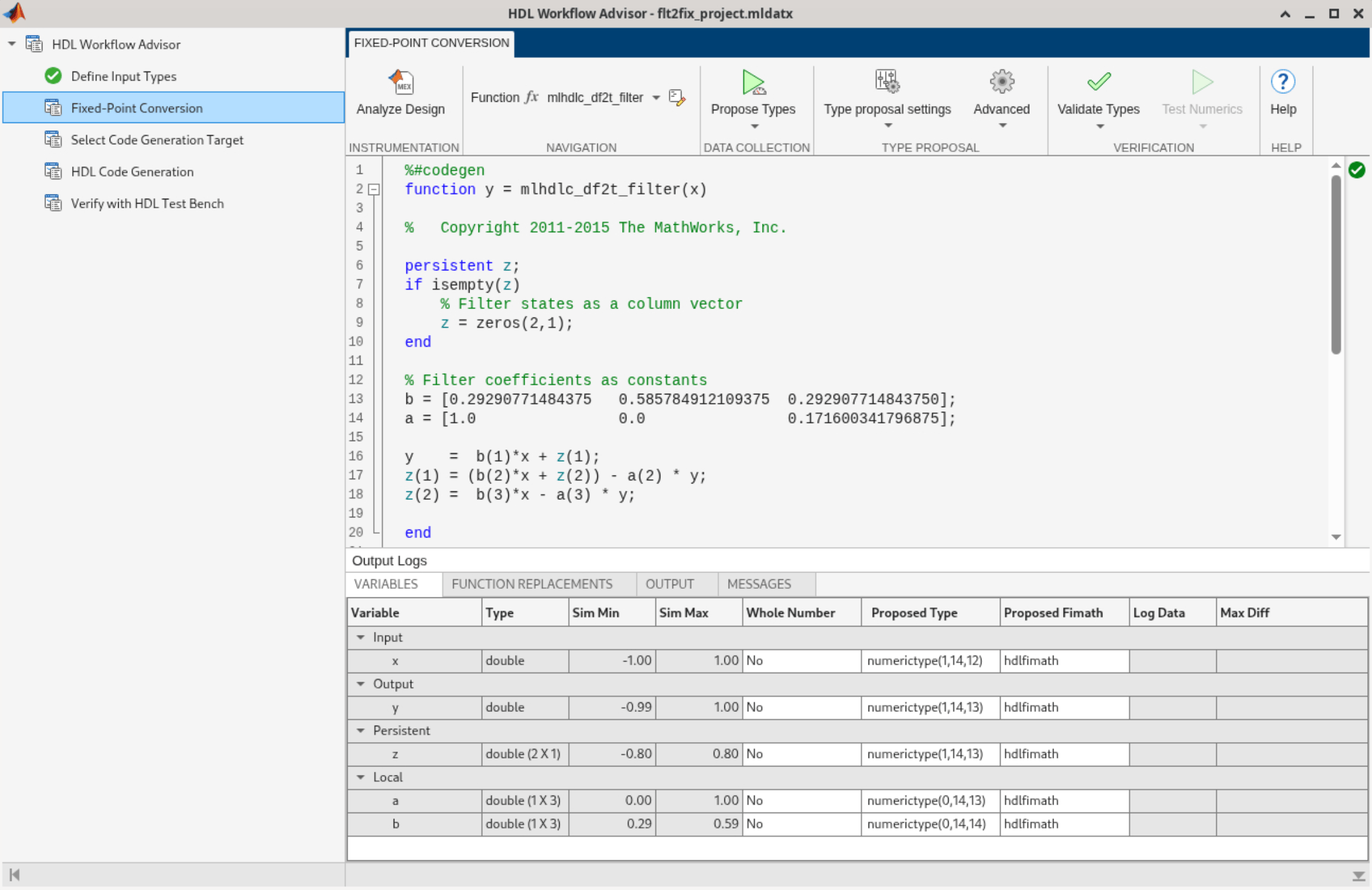
At this stage, based on the computed simulation ranges for all variables, you can compute:
Fraction lengths for a given fixed word length setting, or
Word lengths for a given fixed fraction length setting.
The Variables tab contains this information for each variable that exists in the floating-point MATLAB design, organized by function.
The Sim Min column is the minimum value assigned to the variable during simulation. The Sim Max column is the maximum value assigned to the variable during simulation. The Whole Number column indicates whether all values assigned during the simulation are integers.
The Proposed Type column uses this information and combines it with the user-specified type proposal settings in the Type Proposal pane to propose a fixed-point type for each variable.
Step 4: Validate Types
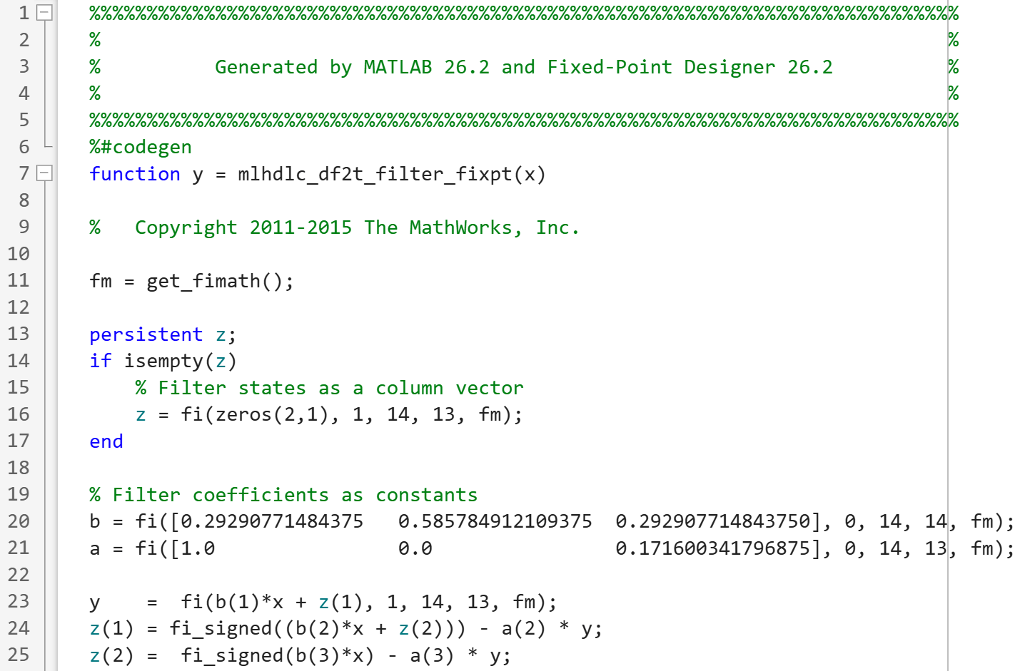
Click Validate Types. The app uses the fixed-point types from the previous step to generate a fixed-point MATLAB design from the original floating-point design.
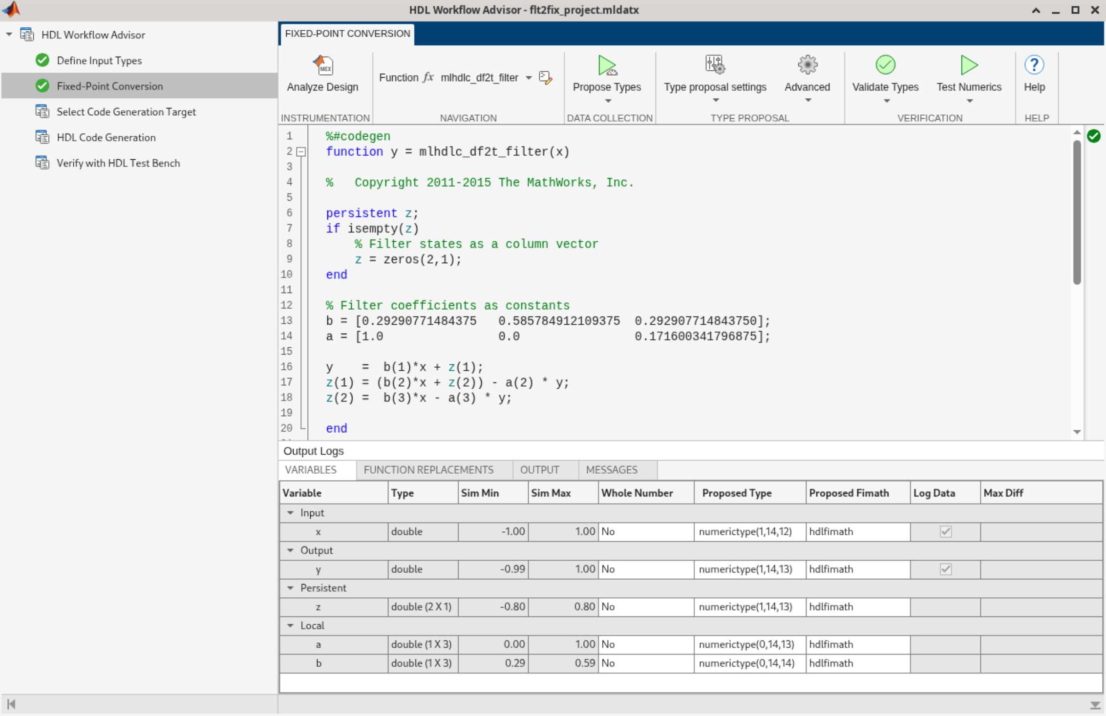
The generated code and other conversion artifacts are accessible with hyperlinks in the Output tab.
Click the mlhdlc_df2t_filter_fixpt link. The fixed-point types are shown in the generated MATLAB code.
Step 5: Test Numerics
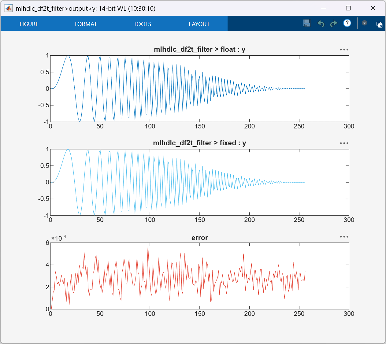
To generate plots for each scalar output that show the floating-point and fixed-point results, as well as the difference between the two, in Test Numerics > Plotting and Reporting, select Log all inputs and outputs for comparison plots.
For non-scalar outputs, the app only plots the error information.
Next, click Test Numerics. The app runs the generated fixed-point code and generates the comparison plots.
Step 6: Iterate on the Results
If the numerical results do not meet your desired accuracy after fixed-point simulation, adjust the settings in the Type Proposal pane or individually modify the types as desired, and repeat the rest of the steps in the workflow until you achieve your desired results.
For more information about how to iterate and refine the numerics of the algorithm in the generated fixed-point code, see Refine Fixed-Point Data Types Using the HDL Workflow Advisor.
See Also
coder.FixPtConfig | Workflow Advisor

