Main Content

Probability Hypothesis Density (PHD) Tracker

Multi-sensor, multi-object PHD tracker

Since R2021a

  • Probability Hypothesis Density Tracker block

Libraries:
Sensor Fusion and Tracking Toolbox / Multi-Object Tracking Algorithms

Description

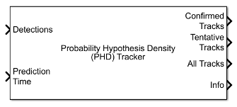
The Probability Hypothesis Density (PHD) Tracker block creates and manages tracks of stationary and moving objects in a multi-sensor environment. The tracker uses a multi-target probability hypothesis density filter to estimate the states of point targets and extended objects. The PHD is represented by a weighted summation of probability density functions, and peaks in the PHD are extracted to represent possible targets. See Algorithms for more details.

Ports

Input

expand all

Detection list, specified as a Simulink bus containing a MATLAB structure. The structure has the form:

FieldDescriptionType
NumDetectionsNumber of detectionsInteger.
DetectionsObject detectionsArray of object detection structures. The first NumDetections of these detections are actual detections.

The fields of Detections are:

FieldDescriptionType
TimeMeasurement timesingle or double
MeasurementObject measurementssingle or double
MeasurementNoiseMeasurement noise covariance matrixsingle or double
SensorIndexUnique ID of the sensorsingle or double
ObjectClassIDObject classification IDsingle or double
MeasurementParametersParameters used by initialization functions of tracking filtersSimulink Bus
ObjectAttributesAdditional information passed to trackerSimulink Bus

See objectDetection for more detailed explanations of these fields.

Note

The object detection structure contains a Time field. The time tag of each object detection must be less than or equal to the time of the current invocation of the block. The time tag must also be greater than the update time specified in the previous invocation of the block.

Track update time, specified as a real scalar in seconds. The tracker updates all tracks to this time. The update time must increase with each invocation of the block. Units are in seconds. The update time must be at least as large as the largest Time specified at the Detections input port.

If this port is not enabled, the simulation clock managed by Simulink determines the update time.

Dependencies

To enable this port, in the Port Setting tab, set Prediction time source to Input port.

Configurations of tracking sensors, specified as a Simulink bus containing a MATLAB structure. The structure has the form:

FieldDescriptionType
NumConfigurationsNumber of sensor configurationsInteger.
ConfigurationsSensor configurations

Array of sensor configuration structures. The first NumConfigurations of these configurations are actual configurations. The field names and definitions must correspond to names and values, respectively, of properties of the trackingSensorConfiguration object.

If you use a Radar Data Generator (Radar Toolbox) block in the tracking system, you can directly specify this value by using the Configuration output of the Radar Data Generator (Radar Toolbox) block, instead.

Dependencies

To enable this port, in the Tracker tab, select the Update sensor configurations with time parameter.

Track state parameters, specified as a Simulink bus containing a MATLAB structure. The structure has the form:

FieldDescription
NumParametersNumber of non-default state parameters, specified as a nonnegative integer
ParametersArray of state parameter structures

The block uses the value of the Parameters field for the StateParameters field of the generated tracks. You can use these parameters to define the reference frame in which the track is reported or other desirable attributes of the generated tracks.

For example, you can use the following structure to define a rectangular reference frame whose origin position is at [10 10 0] meters and whose origin velocity is [2 -2 0] meters per second with respect to the scenario frame.

Field NameValue
Frame"Rectangular"
Position[10 10 0]
Velocity[2 -2 0]

Dependencies

To enable this port, in the Tracker Configuration tab, select the Update track state parameters with time parameter.

Output

expand all

Confirmed tracks, returned as a Simulink bus containing a MATLAB structure. The structure has the form:

FieldDescription
NumTracksNumber of tracks.
TracksArray of track structures of a length set by the Maximum number of tracks parameter. Only the first NumTracks of these are actual tracks.

The fields of the track structure are shown in Track Structure.

Tentative tracks, returned as a Simulink bus containing a MATLAB structure. A track is tentative before it is confirmed. The output of this port has the same form as the output of the Confirmed Tracks port.

Dependencies

To enable this port, in the Port Setting tab, select Enable tentative tracks output.

Combined list of confirmed and tentative tracks, returned as a Simulink bus containing a MATLAB structure. The output of this port has the same form as the output of the Confirmed Tracks port.

Dependencies

To enable this port, in the Port Setting tab, select Enable all tracks output.

Additional information for analyzing track updates, returned as a Simulink bus containing a MATLAB structure.

This table shows the fields of the info structure:

FieldDescription
CorrectionOrder

The order in which sensors are used for state estimate correction, returned as a row vector of SensorIndex values. For example, [1 3 2 4].

TrackIDsAtStepBeginning

Track IDs when the step began.

DeletedTrackIDs

IDs of tracks deleted during the step.

TrackIDsAtStepEnd

Track IDs when the step ended.

SensorAnalysisInfo

Cell array of sensor analysis information.

The SensorAnalysisInfo field can include multiple sensor information reports. Each report is a structure containing these fields:

FieldDescription
SensorIndex

Sensor index.

DetectionCells

Detection cells, returned as a logical matrix. Each column of the matrix denotes a detection cell. In each column, if the ith element is 1, then the ith detection belongs to the detection cell denoted by that column.

DetectionLikelihoods

The association likelihoods between components in the density function and detection cells, returned as an N-by-P matrix. N is the number of components in the density function, and P is the number of detection cells.

IsBirthCells

Indicates if the detection cells listed in DetectionCells give birth to new tracks, returned as a 1-by-P logical vector, where P is the number of detection cells.

NumPartitions

Number of partitions.

DetectionProbability

Probability of existing tracks being detected by the sensor, returned as a 1-by-N row vector, where N is the number of components in the density function.

LabelsBeforeCorrection

Labels of components in the density function before correction, return as a 1-by-Mb row vector. Mb is the number of components maintained in the tracker before correction. Each element of the vector is a TrackID. For example, [1 1 2 0 0]. Note that multiple components can share the same TrackID.

LabelsAfterCorrection

Labels of components in the density function after correction, returned as a 1-by-Ma row vector. Ma is the number of components maintained in the tracker after correction. Each element of the vector is a TrackID. For example, [1 1 1 2 2 0 0]. Note that multiple components can share the same TrackID.

WeightsBeforeCorrection

Weights of components in the density function before correction, returned as a 1-by-Mb row vector. Mb is the number of components maintained in the tracker before correction. Each element of the vector is the weight of the corresponding component in LabelsBeforeCorrection. For example, [0.1 0.5 0.7 0.3 0.2].

WeightsAfterCorrection

Weights of components in the density function after correction, returned as a 1-by-Ma row vector. Ma is the number of components maintained in the tracker after correction. Each element of the vector is the weight of the corresponding component in LabelsAfterCorrection. For example, [0.1 0.4 0.2 0.6 0.3 0.2 0.2].

Dependencies

To enable this port, in the Port Setting tab, select Enable information output.

Parameters

expand all

Tracker Configuration

Specify the unique tracker identifier as a nonnegative integer. This parameter is passed as the SourceIndex in the tracker outputs, and distinguishes tracks that come from different trackers in a multiple-tracker system. You must specify this property as a positive integer to use the track outputs as inputs to a Track-To-Track Fuser block.

Example: 1

Function to partition detections into detection cells, specified as a function name. When each sensor can report more than one detection per object, you must use a partition function. The partition function reports all possible partitions of the detections from a sensor. In each partition, the detections are separated into mutually exclusive detection cells, assuming that each detection cell belongs to one extended object.

You can also specify your own detections partition function. For guidance in writing this function, you can examine the details of the default partitioning function, partitionDetections, using the type command:

type partitionDetections

Example: myfunction

Threshold of selecting detections for component initialization, specified as a positive scalar. During correction, the tracker calculates the likelihood of association between existing tracks and detection cells. If the association likelihood (given by negative log-likelihood) of a detection cell to all existing tracks is higher than the threshold (which means the detection cell has low likelihood of association to existing tracks), the detection cell is used to initialize new components in the adaptive birth density.

Example: 18.1

Data Types: single | double

Maximum number of sensors that can be connected to the tracker, specified as a positive integer. MaxNumSensors must be greater than or equal to the largest value of SensorIndex found in all the detections used to update the block.

Data Types: single | double

Maximum number of tracks that the tracker can maintain, specified as a positive integer.

Data Types: single | double

Maximum number of components that the tracker can maintain, specified as a positive integer.

Data Types: single | double

Configuration of tracking sensors, specified as a structure or an array of structures. This parameter provides the tracking sensor configuration information, such as sensor detection limits and sensor resolution, to the tracker. The allowable field names of each structure are the same as the property names of the trackingSensorConfiguration object. If you set the MaxDetsPerObject field of the structure to 1, the tracker creates only one partition, such that at most one detection can be assigned to each target.

You can update the configuration through the Sensor configurations input port by selecting the Update sensor configurations with time parameter.

Select this parameter to enable the input port for tracking sensor configurations through the Sensor Configurations input port.

Specify the parameters of the track state reference frame as a structure or a structure array. The block passes the value of this parameter to the StateParameters field of the generated tracks. You can use these parameters to define the reference frame in which the track is reported or other desirable attributes of the generated tracks.

For example, you can use the following structure to define a rectangular reference frame whose origin position is at [10 10 0] meters and whose origin velocity is [2 -2 0] meters per second with respect to the scenario frame.

Field NameValue
Frame"Rectangular"
Position[10 10 0]
Velocity[2 -2 0]

You can update the track state parameters through the State Parameters input port by selecting the Update track state parameters with time parameter.

Data Types: struct

Select this parameter to enable the input port for track state parameters through the State Parameters input port.

Select the type of simulation to run from these options:

  • Interpreted execution — Simulate the model using the MATLAB interpreter. This option shortens startup time. In the Interpreted execution mode, you can debug the source code of the block.

  • Code generation — Simulate the model using generated C code. The first time you run a simulation, Simulink generates C code for the block. The C code is reused for subsequent simulations as long as the model does not change. This option requires additional startup time.

Track Management

Birth rate of new targets in the density, specified as a positive real scalar. Birth rate indicates the expected number of targets added in the density per unit time. The birth density is created by using the FilterInitializationFcn of the sensor configuration used with the tracker. In general, the tracker adds components to the density function in two ways:

  1. Predictive birth density — This density is initialized by the FilterInitializationFcn function when called with no inputs.

  2. Adaptive birth density — This density is initialized by the FilterInitializationFcn function when called with detection inputs. The tracker chooses detections based on their log-likelihood of association with the current estimates of the targets.

The value for the Birth rate of new targets parameter represents the summation of both predictive birth density and adaptive birth density for each time step.

Example: 0.01

Data Types: single | double

Death rate of components in the density, specified as a positive real scalar. Death rate indicates the rate at which a component vanishes in the density after one time step. This equation illustrates how death rate (Pd) relates to the survival probability (Ps) of a component between successive time steps:

Ps=(1Pd)ΔT

where ΔT is the time step.

Example: 1e-4

Data Types: single | double

Threshold for initializing a tentative track, specified as a positive real scalar. If the weight of a component is higher than the threshold, the component is labeled as a 'Tentative' track and given a TrackID.

Example: 0.45

Data Types: single | double

Threshold for track confirmation, specified as a positive real scalar. In a PHD tracker, a track can have multiple components sharing the same TrackID. If the weight summation of the components of a tentative track is higher than the confirmation threshold, the track status is marked as 'Confirmed'.

Example: 0.85

Data Types: single | double

Threshold for component deletion, specified as a positive real scalar. In the PHD tracker, if the weight of a component is lower than the deletion threshold, the component is deleted.

Example: 0.01

Data Types: single | double

Threshold for components merging, specified as a positive real scalar. In the PHD tracker, if the Kullback-Leibler distance between components with the same TrackID is smaller than the merging threshold, then these components are merged into one component. The merged weight of the new component is equal to the summation of the weights of the pre-merged components. Moreover, if the merged weight is higher than the first threshold specified in the Thresholds for label management parameter, the merged weight is truncated to the first threshold. Note that components with a TrackID of 0 can also be merged with each other.

Example: 30

Data Types: single | double

Labeling thresholds, specified as an 1-by-3 vector of decreasing positive values, [C1, C2, C3]. Based on this parameter, the tracker manages components in the density using these rules:

  1. The weight of any component that is higher than the first threshold C1 is reduced to C1.

  2. For all components with the same TrackID, if the largest weight among these components is greater than C2, then the component with the largest weight is preserved to retain the TrackID, while all other components are deleted.

  3. For all components with the same TrackID, if the ratio of the largest weight to the weight summation of all these components is greater than C3, then the component with the largest weight is preserved to retain the TrackID, while all other components are deleted.

  4. If neither condition 2 nor condition 3 is satisfied, then the component with the largest weight retains the TrackID, while the labels of all other components are set to 0. When this occurs, it means that some components may represent other objects. This process retains the possibility for these unreserved components to be extracted again in the future.

Port Setting

Source for prediction time, specified as Input port or Auto. Select Input port to input an update time by using the Prediction Time input port. Otherwise, the simulation clock managed by Simulink determines the update time.

Select this parameter to enable the output of tentative tracks through the Tentative Tracks output port.

Select this parameter to enable the output of all tracks through the All Tracks output port.

Select this parameter to enable the output of analysis information through the Info output port.

Source of the output track bus name, specified as:

  • Auto — The block automatically creates an output track bus name.

  • Property — Specify the output track bus name by using the Specify an output bus name parameter.

Source of the output information bus name, specified as:

  • Auto — The block automatically creates an output information bus name.

  • Property — Specify the output information bus name by using the Specify an output info bus name parameter.

Dependencies

To enable this parameter, on the Port Setting tab, select Enable information output.

Algorithms

expand all

References

[1] Granstorm, K., C. Lundquiest, and O. Orguner. " Extended target tracking using a Gaussian-mixture PHD filter." IEEE Transactions on Aerospace and Electronic Systems. Vol. 48, Number 4, 2012, pp. 3268-3286.

[2] Granstorm, K., and O. Orguner." A PHD filter for tracking multiple extended targets using random matrices." IEEE Transactions on Signal Processing. Vol. 60, Number 11, 2012, pp. 5657-5671.

[3] Granstorm, K., and A. Natale, P. Braca, G. Ludeno, and F. Serafino."Gamma Gaussian inverse Wishart probability hypothesis density for extended target tracking using X-band marine radar data." IEEE Transactions on Geoscience and Remote Sensing. Vol. 53, Number 12, 2015, pp. 6617-6631.

[4] Panta, Kusha, et al. “Data Association and Track Management for the Gaussian Mixture Probability Hypothesis Density Filter.” IEEE Transactions on Aerospace and Electronic Systems, vol. 45, no. 3, July 2009, pp. 1003–16.

[5] Ristic, B., et al. “Adaptive Target Birth Intensity for PHD and CPHD Filters.” IEEE Transactions on Aerospace and Electronic Systems, vol. 48, no. 2, 2012, pp. 1656–68.

Extended Capabilities

Version History

Introduced in R2021a

expand all