Main Content

monostaticLidarSensor

Simulate and model lidar point cloud generator

Since R2020b

Description

The monostaticLidarSensor System object™ generates point cloud detections of targets by a monostatic lidar sensor. You can use the monostaticLidarSensor object in a scenario containing moving and stationary platforms such as one created using trackingScenario. The monostaticLidarSensor object generates point clouds from platforms with defined meshes (using the Mesh property). The monostaticLidarSensor System object models an ideal point cloud generator and does not account for the effects of false alarms and missed detections.

To generate point cloud detections using a simulated lidar sensor:

  1. Create the monostaticLidarSensor object and set its properties.

  2. Call the object with arguments, as if it were a function.

To learn more about how System objects work, see What Are System Objects?

Creation

Description

example

sensor = monostaticLidarSensor(SensorIndex) creates a simulated lidar sensor with a specified sensor index, SensorIndex. Default property values are used.

sensor = monostaticLidarSensor(SensorIndex,Name,Value) sets properties using one or more name-value pairs. Enclose each property name in quotes. For example, monostaticLidarSensor(1,'DetectionCoordinates','Sensor') creates a simulated lidar sensor that reports detections in the sensor Cartesian coordinate system with sensor index equal to 1.

Properties

expand all

Unless otherwise indicated, properties are nontunable, which means you cannot change their values after calling the object. Objects lock when you call them, and the release function unlocks them.

If a property is tunable, you can change its value at any time.

For more information on changing property values, see System Design in MATLAB Using System Objects.

Unique sensor identifier, specified as a positive integer. This property distinguishes point clouds generated from different sensors in a multi-sensor system. When creating a monostaticLidarSensor system object, you must either specify the SensorIndex as the first input argument in the creation syntax, or specify it as the value for the SensorIndex property in the creation syntax.

Sensor update rate, specified as a positive scalar in Hz. The update interval (reciprocal of the UpdateRate) must be an integer multiple of the simulation time interval defined in trackingScenario. Any update requested to the sensor between update intervals contains no point clouds.

Example: 5

Data Types: double

Sensor location on platform, specified as a 1-by-3 real-valued vector. This property defines the coordinates of the sensor with respect to the platform origin. The default value specifies that the sensor origin is 1.5 meters forward of the platform origin. Units are in meters.

Example: [.2 0.1 0]

Data Types: double

Sensor mounting orientation on the platform, specified as a 3-element vector of scalars in degrees. Each element of the vector corresponds to an intrinsic Euler angle rotation that carries the body axes of the platform to the sensor axes. The three elements define the rotations around the z-, y-, and x-axes, in that order. The first rotation rotates the platform axes around the z-axis. The second rotation rotates the frame around the rotated y-axis. The final rotation rotates the frame around the carried x-axis.

Example: [10 20 -15]

Data Types: double

Maximum detection range, specified as a positive scalar in meters.

Example: 500

Data Types: double

Accuracy of range measurements, specified as a positive scalar in meters. The property value represents the standard deviation of the range measurements.

Example: 0.1

Data Types: double

Azimuth resolution of the lidar sensor, specified as a positive scalar in degrees. The number of points per elevation channel is equal to the azimuth limits divided by the azimuth resolution.

Data Types: double

Elevation resolution of the lidar sensor, specified as a positive scalar in degrees. The number of points per azimuth channel is equal to the elevation limits divided by the elevation resolution.

Data Types: double

Azimuth limits of the lidar sensor, specified as a 1-by-2 row vector of scalars in degrees.

Example: [-90 90]

Data Types: double

Elevation limits of the lidar sensor, specified as a 1-by-2 row vector of scalars in degrees.

Example: [-90 90]

Data Types: double

Enable addition of noise to point cloud locations, specified as true or false. Set this property to true to add noise to point cloud locations. Otherwise, the point cloud locations contain no noise. The sensor adds random Gaussian noise to each point with mean equal to zero and standard deviation specified by the RangeAccuracy property.

Data Types: logical

Enable organized point cloud locations, specified as true or false.

  • When this property is set as true, the point cloud output is an N-by-M-by-3 array of scalars, where N is the number of elevation channels, and M is the number of azimuth channels.

  • When this property is set as false, the point cloud output is an P-by-3 matrix of scalars, where P is the product of the numbers of elevation and azimuth channels.

Data Types: logical

Enable the optional input argument that passes the current INS estimate of the sensor platform pose to the sensor, specified as false or true. When true, the pose information is added to the MeasurementParameters property of the configuration, enabling tracking and fusion algorithms to estimate the state of the targets in the scenario frame. It also enables to report the point cloud locations in the scenario frame.

Data Types: logical

Coordinate system in which the detections are reported, specified as:

  • 'Sensor' — Detections are reported in the sensor's rectangular coordinate system.

  • 'Body' — Detections are reported in the rectangular body system of the platform.

  • 'Scenario' — Detections are reported in the rectangular scenario coordinate frame. To enable this value, set the HasINS property to true.

Data Types: char

Usage

Description

pointCloud = sensor(targetMeshes,time) returns point cloud measurements from the 3-D geometric meshes of targets, tgtMeshes, at the simulation time.

pointCloud = sensor(targetMeshes,insPose,time) also specifies the INS-estimated pose, insPose, for the sensor platform. INS information is used by tracking and fusion algorithms to estimate the target positions in the scenario frame.

To enable this syntax, set the HasINS property to true.

[pointCloud,config] = sensor(___) also returns the configuration of the sensor, config, at the current simulation time. You can use these output arguments with any of the previous input syntaxes.

[pointCloud,config,clusters] = sensor(___) also returns clusters, the true cluster labels for each point in the point cloud.

Input Arguments

expand all

Meshes of targets, specified as an array of structures. Each structure must contain the following fields.

Field NameDescription
PlatformIDUnique identifier of the target, specified as a nonnegative integer.
ClassIDUnique identifier of the class of the target, specified as a nonnegative integer.
PositionPosition of the target with respect to the sensor mounting platform's body frame, specified as a 3-element vector of scalars.
OrientationOrientation of the target with respect to the sensor mounting platform's body frame, specified as a quaternion object or a rotation matrix.
MeshGeometric mesh of the target, specified as an extendedObjectMesh object with respect to the target's body frame.

Platform pose from INS estimation, specified as a structure. The INS information can be used by tracking and fusion algorithms to estimate the platform's pose and velocity in the scenario frame.

Platform pose information from an inertial navigation system (INS) is a structure with these fields:

FieldDefinition
Position

Position in the navigation frame, specified as a real-valued 1-by-3 vector. Units are in meters.

Velocity

Velocity in the navigation frame, specified as a real-valued 1-by-3 vector. Units are in meters per second.

Orientation

Orientation with respect to the navigation frame, specified as a quaternion or a 3-by-3 real-valued rotation matrix. The rotation is from the navigation frame to the current INS body frame. This is also referred to as a "parent to child" rotation.

Dependencies

To enable this argument, set the HasINS property to true.

Data Types: struct

Current simulation time, specified as a positive scalar in seconds.

Data Types: double

Output Arguments

expand all

Point cloud detections generated by the sensor, return as an array of scalars. The dimension of the array is determined by the HasOrganizedOuput property.

  • When the property is set as true, pointClouds is returned an N-by-M-by-3 array of scalars, where N is the number of elevation channels, and M is the number of azimuth channels.

  • When the property is set as false, pointClouds is returned as an P-by-3 matrix of scalars, where P is the product of the numbers of elevation and azimuth channels.

The coordinate frame in which the point cloud locations are reported is determined by the DetectionCoordinates property.

Current sensor configuration, returned as a structure. The structure has these fields:

FieldDescription
SensorIndex

Unique sensor index, returned as a positive integer.

IsValidTime

Valid detection time, returned as true or false. IsValidTime is false when detection updates are requested between update intervals specified by the update rate.

IsScanDone

IsScanDone is true when the sensor has completed a scan.

FieldOfView

Field of view of the sensor, returned as a 2-by-2 matrix of positive real values. The first row elements are the lower and upper azimuth limits; the second row elements are the lower and upper elevation limits.

MeasurementParameters

Sensor measurement parameters, returned as an array of structures containing the coordinate frame transforms needed to transform positions and velocities in the top-level frame to the current sensor frame.

Data Types: struct

Cluster labels of points in the pointCloud output, returned as an array of nonnegative integers. The dimension of the array is determined by the HasOrganizedOuput property.

  • When this property is set as true, cluster is returned as an N-by-M-by-2 array of scalars, where N is the number of elevation channels, and M is the number of azimuth channels. On the third dimension, the first element represents the PlatformID of the target generating the point, and the second element represents the ClassID of the target.

  • When this property is set as false, pointClouds is returned as a P-by-2 matrix of scalars, where P is the product of the numbers of elevation and azimuth channels. For each row of the matrix, the first element represents the PlatformID of the target generating the point whereas the second element represents the ClassID of the target.

Object Functions

To use an object function, specify the System object as the first input argument. For example, to release system resources of a System object named obj, use this syntax:

release(obj)

expand all

coverageConfigSensor and emitter coverage configuration
perturbApply perturbations to object
perturbationsPerturbation defined on object
stepRun System object algorithm
releaseRelease resources and allow changes to System object property values and input characteristics
resetReset internal states of System object

Examples

collapse all

Create a tracking scenario. Add an ego platform and a target platform.

scenario = trackingScenario;

ego = platform(scenario);
target = platform(scenario,'Trajectory',kinematicTrajectory('Position',[10 -3 0],'Velocity',[5 0 0]));

Define the geometric mesh of the target. The size of the mesh is adjusted after specifying the target dimensions.

target.Mesh = extendedObjectMesh('sphere');
target.Dimensions.Length = 5; 
target.Dimensions.Width = 3;
target.Dimensions.Height = 2;

Visualize the mesh of the target.

show(target.Mesh)

ans = 
  Axes with properties:

             XLim: [-3 3]
             YLim: [-2 2]
           XScale: 'linear'
           YScale: 'linear'
    GridLineStyle: '-'
         Position: [0.1300 0.1100 0.7750 0.8150]
            Units: 'normalized'

  Use GET to show all properties

Create a monostaticLidarSensor with specified UpdateRate and DetectionCoordinates.

sensor = monostaticLidarSensor(1,'UpdateRate',10,'DetectionCoordinates','Body');

Obtain the mesh of the target viewed from the ego platform after advancing the scenario one step forward.

advance(scenario);
tgtmeshes = targetMeshes(ego);

Use the created sensor to generate point clouds from the obtained target mesh.

time = scenario.SimulationTime;
[ptCloud, config, clusters] = sensor(tgtmeshes, time);

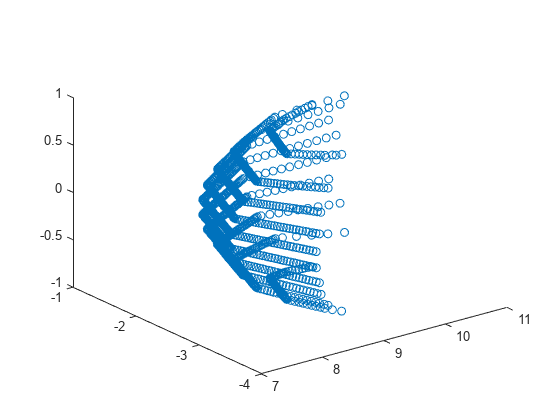
Visualize the point cloud detections.

figure()
plot3(ptCloud(:,1),ptCloud(:,2),ptCloud(:,3),'o')

Version History

Introduced in R2020b