Design Event-Based Simulink Model
Design models for algorithms that handle asynchronous events such as hardware-generated interrupts. These models support execution of blocks in response to events that are asynchronous with respect to the periodic timing source of the system. For example, a peripheral device might signal completion of an input operation by generating an interrupt. The system must service such interrupts, for example, by acquiring data from the interrupting device.
To create and configure an event-based Simulink model:
Create a new blank model.
Configure the model for Infineon AURIX hardware board.
In the Simulink editor, press Ctrl+E or click Modeling > Model Settings to open the Configuration Parameters dialog box.
Select the Hardware Implementation pane and set Hardware board to
Infineon AURIX
                     TC4x
and Processing Unit toPPU.Select the Model Referencing pane and set Total number of instances allowed per top model to
One.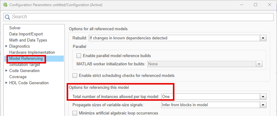
If your application algorithm involves highly parallel vector computations, PPU can speed up the computation by using the code replacement libraries for optimized code generation. To use such library, go to Code Generation > Interface > Code replacement libraries and click Select. Then select a CRL from the libraries available for the PPU core of Infineon TC4x microcontrollers. For more information, see Parallel Processing Unit for Optimized Code Generation.

Save the model. For example, save as
ifx_ppu.slx.Create an asynchronous task for the event-based model.
In the Simulink editor, add a Function-Call Subsystem block to the model. Connect an Inport block to the input port and an Outport block to the port of the Function-Call Subsystem block.

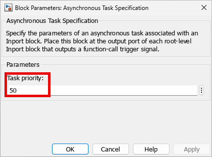
Add an Asynchronous Task Specification block to the model. The task priority value must be set greater than 40 as the internal scheduling operates at a priority of 40. Set the Task priority parameter to
50.
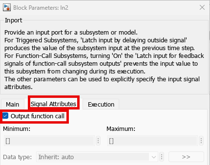
Add an Inport block and double-click it to open Block Parameter dialog box. On the Signal Attributes tab, enable Output function call parameter.
Connect this Inport block to the input port of the Asynchronous Task Specification block.
Connect the output port of Asynchronous Task Specification block to the
function()input of the Function-Call Subsystem block.
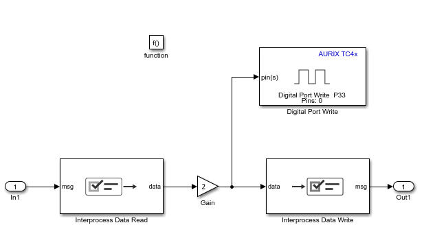
The model now looks similar to the figure.

Open the Function-Call subsystem and add the blocks you need for your application. For example, consider these connections.
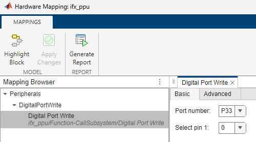
To view and configure the peripheral blocks and their parameters, on the Simulink toolstrip, on the Hardware tab, click Hardware Mapping. For more information, see Map Tasks and Peripherals Using Hardware Mapping
See Also
Blocks
- Interprocess Data Read | Interprocess Data Write | Inport | Outport | Function-Call Subsystem | Asynchronous Task Specification
Tools
Model Settings
- Pre-load TriCore0 with custom executable which enables current processing unit | Total number of instances allowed per top model