FIR Rate Converter
Upsample, filter, and downsample input signal
Libraries:
DSP HDL Toolbox /
Filtering
Description
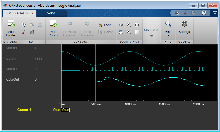
The FIR Rate Converter block upsamples, filters, and downsamples input signals. It is optimized for HDL code generation and operates on one sample of each channel at a time. The block implements a polyphase architecture to avoid unnecessary arithmetic operations and high intermediate sample rates.
The block upsamples the input signal by an integer factor of L, applies it to a FIR filter, and downsamples the input signal by an integer factor of M.
You can use the input and output control ports to pace the flow of samples. In the default configuration, the block uses input and output valid control signals. For additional flow control, you can enable a ready output signal.
The ready output port indicates that the block can accept a new input
data sample on the next time step. When L ≥ M, you can
use the ready signal to achieve continuous output data samples. If you
apply a new input sample after each time the block returns ready signal
as 1
, the block returns a data output sample with the output
valid signal set to 1
on every time step.
When you disable the ready port, you can apply a valid data sample
only every ceil(L/M)
time steps. For example, if:
L/M = 4/5, then you can apply a new input sample on every time step.
L/M = 3/2, then you can apply a new input sample on every other time step.
Examples
Ports
Input
data — Input data sample
scalar | row vector
Input data sample, specified as a scalar, or as a row vector in which each element represents an independent channel. The block accepts real or complex data.
The software supports double
and
single
data types for simulation, but not for HDL code generation.
Data Types: single
| double
| int8
| int16
| int32
| int64
| uint8
| uint16
| uint32
| uint64
| fixed point
Complex Number Support: Yes
valid — Indicates valid input data
scalar
Control signal that indicates if the input data is valid. When
valid is 1
(true
), the
block captures the values from the input data port. When
valid is 0
(false
), the
block ignores the values from the input data port.
You can apply a valid data sample every ceiling(L/M)
time
steps.
Data Types: Boolean
Output
data — Output data sample
scalar | row vector
Output data sample, returned as a scalar or a row vector in which each element represents an independent channel.
Data Types: single
| double
| int8
| int16
| int32
| int64
| uint8
| uint16
| uint32
| uint64
| fixed point
Complex Number Support: Yes
valid — Indicates valid output data
scalar
Control signal that indicates if the data from the output
data port is valid. When valid is
1
(true
), the block returns valid data from
the output data port. When valid is
0
(false
), the values from the output
data port are not valid.
Data Types: Boolean
ready — Indicates block is ready for new input data
scalar
Control signal that indicates that the block is ready for new input data sample on
the next cycle. When ready is 1
(true
), you can specify the data
and valid inputs for the next time step. When
ready is 0
(false
), the block ignores any input data in the next time step.
Dependencies
To enable this port, select the Enable ready output port check box.
Data Types: Boolean
Parameters
Main
Interpolation factor — Interpolation factor
3
(default) | positive integer
Specify a factor by which the block interpolates the input data sample.
Decimation factor — Decimation factor
2
(default) | positive integer
Specify a factor by which the block decimates the input data sample.
FIR filter coefficients — FIR filter coefficients
firpm(70, [0 0.28 0.32 1],[1 1 0 0])
(default) | row vector
Specify a row vector of coefficients in descending powers of z-1.
You can also specify the coefficients as a workspace variable or as a call to the
Signal Processing Toolbox™ filter design functions (such as fir1
). Design a
lowpass filter with normalized cutoff frequency no greater than
min(1/L,1/M)
. The block initializes internal filter states to
zero.
When the input data type is a floating-point type, the block casts the coefficients to the same data type as the input. When the input data type is an integer type or a fixed-point type, set the data type of the coefficients on the Data Types tab.
Data Types
Rounding mode — Rounding mode for fixed-point operation
Floor
(default) | Ceiling
| Convergent
| Nearest
| Round
| Zero
Select a rounding mode for fixed-point operations. For more information, see Rounding mode.
Saturate on integer overflow — Method of overflow action
off
(default) | on
Specify whether overflows saturate or wrap.
off
— Overflows wrap to the appropriate value that data type can represent. For example, because 130 does not fit in a signed 8-bit integer, it wraps to -126.on
— Overflows saturate to either the minimum or maximum value that data type can represent. For example, an overflow associated with a signed 8-bit integer can saturate to -128 or 127.
Coefficients — FIR filter coefficients data type
fixdt(1,16,16)
(default)
FIR filter coefficients data type, specified as a
fixdt(s,wl,fl)
object with signedness
,
word length
, and fractional length
properties.
When the input is a fixed-point or integer type, the block casts the filter
coefficients using the rule or data type in this parameter. The quantization rounds to
the nearest representable value and saturates on overflow. When the input data type is
a floating-point type, the block ignores this parameter and all internal arithmetic
uses the same data type as the input.
Output — Data type of output data sample
Inherit: Same word length as input
(default) | Inherit via internal rule
| fixdt(s,wl,fl)
When the input is a fixed-point or integer type, the block casts the output of the filter using the rule or data type in this parameter. The quantization uses the settings of the Rounding mode and Overflow mode parameters. When the input data type is floating point, the block ignores this parameter and returns output in the same data type as the input.
Control Ports
Enable ready output port — Option to enable ready control signal
off
(default) | on
Select this parameter to enable the ready port.
Algorithms
The FIR Rate Converter block implements a fully parallel polyphase filter architecture. The diagram shows where the block casts the data types based on your configuration.
Delay
Because the block models HDL pipeline latency, an initial delay of several time steps exists before the block returns the first valid output data sample. The latency depends on the filter coefficients and the resampling factors. To determine the latency from the first input data sample to the first output data sample, measure the cycles between asserting the input valid signal and the output valid signal going high.
Performance
For an example of design performance, generate HDL for the block as configured in the Control Data Rate Using Ready Signal example. The example filter resamples at 5/2, and uses a symmetric 71-tap filter. The input samples and filter coefficients are 16 bits wide. The design is targeted to a Xilinx® Virtex®-6 FPGA, using Xilinx ISE synthesis and place and route tools.
After placement and routing, the design achieves 535 MHz clock frequency and uses these resources of the FPGA device.
LUT | 592 |
FFS | 979 |
Xilinx LogiCORE® DSP48 | 15 |
Block RAM (16K) | 0 |
Performance of the synthesized HDL code varies depending on your filter coefficients, FPGA target, and synthesis options.
Extended Capabilities
C/C++ Code Generation
Generate C and C++ code using Simulink® Coder™.
This block supports C/C++ code generation for Simulink® accelerator and rapid accelerator modes and for DPI component generation.
HDL Code Generation
Generate VHDL, Verilog and SystemVerilog code for FPGA and ASIC designs using HDL Coder™.
HDL Coder™ provides additional configuration options that affect HDL implementation and synthesized logic.
This block has one default HDL architecture.
ConstrainedOutputPipeline | Number of registers to place at
the outputs by moving existing delays within your design. Distributed
pipelining does not redistribute these registers. The default is
|
InputPipeline | Number of input pipeline stages
to insert in the generated code. Distributed pipelining and constrained
output pipelining can move these registers. The default is
|
OutputPipeline | Number of output pipeline stages
to insert in the generated code. Distributed pipelining and constrained
output pipelining can move these registers. The default is
|
Version History
Introduced in R2015bR2022a: Moved to DSP HDL Toolbox from DSP System Toolbox
Before R2022a, this block was named FIR Rate Conversion HDL Optimized and was included in the DSP System Toolbox™ DSP System Toolbox HDL Support library.
R2022a: Remove request port
In previous releases, the block provided an optional request port. This port is no longer available. For an alternate way to control the data rate in your model, see Control Data Rate Using Ready Signal.
R2022a: Synchronous ready signal
The ready signal is now pipelined at the output of the block. In previous releases, the ready output signal was direct feedthrough without an output pipeline register.
MATLAB 명령
다음 MATLAB 명령에 해당하는 링크를 클릭했습니다.
명령을 실행하려면 MATLAB 명령 창에 입력하십시오. 웹 브라우저는 MATLAB 명령을 지원하지 않습니다.
Select a Web Site
Choose a web site to get translated content where available and see local events and offers. Based on your location, we recommend that you select: .
You can also select a web site from the following list:
How to Get Best Site Performance
Select the China site (in Chinese or English) for best site performance. Other MathWorks country sites are not optimized for visits from your location.
Americas
- América Latina (Español)
- Canada (English)
- United States (English)
Europe
- Belgium (English)
- Denmark (English)
- Deutschland (Deutsch)
- España (Español)
- Finland (English)
- France (Français)
- Ireland (English)
- Italia (Italiano)
- Luxembourg (English)
- Netherlands (English)
- Norway (English)
- Österreich (Deutsch)
- Portugal (English)
- Sweden (English)
- Switzerland
- United Kingdom (English)