Single Loop Feedback/Prefilter Compensator Design
This example shows how to tune multiple compensators (feedback and prefilter) to control a single loop using Control System Designer.
Open the Model
Open the engine speed control model and take a few moments to explore it.
open_system('scdspeedctrl')

Design Overview
This example introduces the process of designing a single-loop control system with both feedback and prefilter compensators. The goal of the design is to:
Track the reference signal from a Simulink® step block
scdspeedctrl/Speed Reference. The design requirement is to have a settling time of under 5 seconds and zero steady-state error to the step reference input.Reject an unmeasured output disturbance specified in the subsystem
scdspeedctrl/External Disturbance. The design requirement is to reduce the peak deviation to 190 RPM and to have zero steady-state error for a step disturbance input.
In this example, the stabilization of the feedback loop and the rejection of the output disturbance are achieved by designing the PID compensator scdspeedctrl/PID Controller. The prefilter scdspeedctrl/Reference Filter is used to tune the response of the feedback system to changes in the reference tracking.
Open Control System Designer
This example uses Control System Designer to tune the compensators in the feedback system. To open the Control System Designer
Launch a pre-configured Control System Designer session by double-clicking the subsystem in the lower left corner of the model.
Configure Control System Designer using the following procedure.
Start a New Design
To open Control System Designer, in the Simulink model window, in the Apps gallery, click Control System Designer.
The Edit Architecture dialog box opens when the Control System Designer launches.
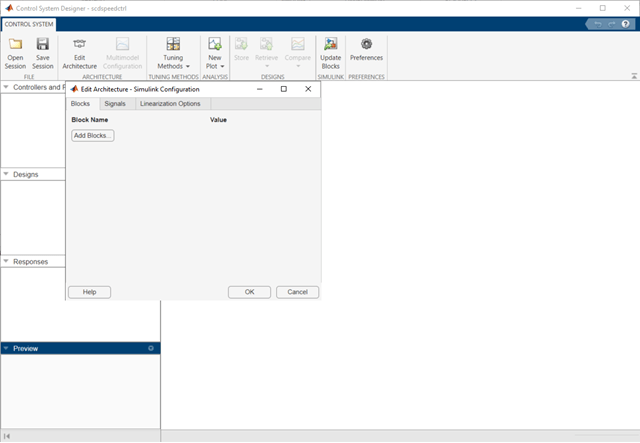
In the Edit Architecture dialog box, on the Blocks tab, click Add Blocks, and select the following blocks to tune:
scdspeedctrl/Reference Filter
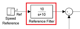
scdspeedctrl/PID Controller

On the Signals tab, the analysis points defined in the Simulink model are automatically added as Locations.
Input:
scdspeedctrl/Speed Referenceoutput port 1
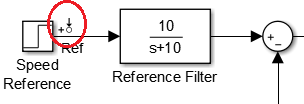
Input
scdspeedctrl/External Disturbance/Step Disturbanceoutput port 1

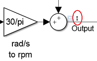
Output
scdspeedctrl/Speed Outputoutput port 1
On the Linearization Options tab, in the Operating Point drop-down list, select Model Initial Condition.
Create new plots to view the step responses while tuning the controllers. In Control System Designer, click New Plot, and select New Step. In the Select Response to Plot drop-down menu, select New Input-Output Transfer Response. Configure the response as follows:
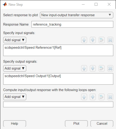
To view the response, click Plot.
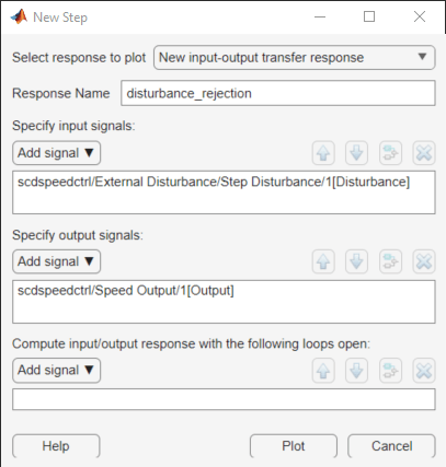
Similarly, create a step response plot to show the disturbance rejection. In the New Step to plot dialog box, configure the response as follows:
Tune Compensators
Control System Designer contains several methods tuning a control system:
Manually tune the parameters of each compensator using the compensator editor. For more information, see Tune Simulink Blocks Using Compensator Editor (Simulink Control Design).
Graphically tune the compensator poles, zeros, and gains using open/closed-loop Bode, root locus, or Nichols editor plots. Click Tuning Methods, and select an editor under Graphical Tuning.
Optimize compensator parameters using both time-domain and frequency-domain design requirements (requires Simulink Design Optimization™ software). Click Tuning Methods, and select Optimization based tuning. For more information, see Enforcing Time and Frequency Requirements on a Single-Loop Controller Design (Simulink Design Optimization).
Compute initial compensator parameters using automated tuning based on parameters such as closed-loop time constants. Click Tuning Methods, and select either PID Tuning, Internal Model Control (IMC) Tuning, Loop Shaping (requires Robust Control Toolbox™ software), or LQG Synthesis.
Completed Design
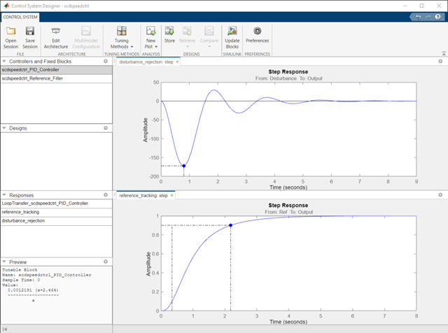
The following compensator parameters satisfy the design requirements:
scdspeedctrl/PID Controllerhas parameters:
         P = 0.0012191
         I = 0.0030038
scdspeedctrl/Reference Filter:
         Numerator = 10
         Denominator = [1 10]
The responses of the closed-loop system are shown below:
Update Simulink Model
To write the compensator parameters back to the Simulink model, click Update Blocks. You can then test your design on the nonlinear model.
bdclose('scdspeedctrl')