Programmatically Initializing the Control System Designer
This example shows how to configure Control System Designer from the command line and how to create functions to customize the startup of a Control System Designer session.
Control System Designer Configurations
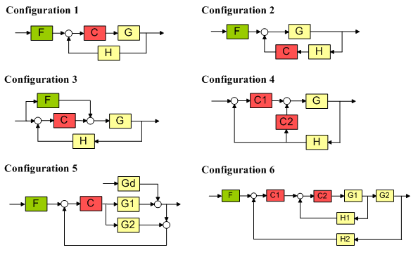
Control System Designer has six available feedback control system configurations:
1) Standard feedback loop with the compensator in the forward path and a prefilter.
2) Standard feedback loop with the compensator in the feedback path and a prefilter.
3) Feedforward compensation and a feedback loop with a compensator in the forward path. This configuration is often used to attenuate disturbances that can be measured before they act on the system.
4) Nested multiloop design configuration. This configuration provides the ability to separate the design into steps by isolating portions of the control loops.
5) The standard Internal Model Control (IMC) structure.
6) Cascaded multiloop design configuration. This configuration provides the ability to separate the design into steps by isolating portions of the control loops.

By default, Control System Designer is initialized with configuration 1. You can change this within the app. Alternatively, you can initialize Control System Designer from the command line.
Initialize Control System Designer
For this example, create a design initialization structure with the following settings:
Feedback configuration 4
Plant
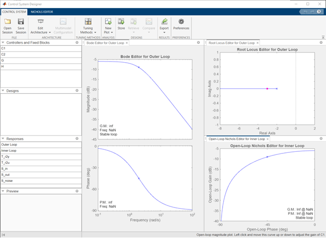
Gwith a value of tf(1,[1,1])Root locus and bode editors for the outer open-loop
Nichols editor for the inner open-loop
Create a design initialization structure for configuration 4 using the sisoinit command.
s = sisoinit(4)
             Name: ''
      Description: 'Design snapshot.'
     FeedbackSign: [2×1 double]
            Input: {4×1 cell}
           Output: {2×1 cell}
          Version: 2
    Configuration: 4
         LoopView: [10×1 sisodata.looptransfer]
               C2: [1×1 sisodata.TunedZPKSnapshot]
                G: [1×1 sisodata.system]
              OL2: [1×1 sisodata.TunedLoopSnapshot]
               C1: [1×1 sisodata.TunedZPKSnapshot]
                H: [1×1 sisodata.system]
              OL1: [1×1 sisodata.TunedLoopSnapshot]
In the initialization structure, s, the system model components are:
Outer-loop compensator -
C1Inner-loop compensator -
C2Plant dynamics -
GSensor dynamics -
H
The loop editor configurations for the system are:
Outer loop - OL1
Inner loop - OL2
Specify the value of the plant.
s.G.Value = tf(1,[1,1]);
Specify the editors to use for each open loop and meaningful loop names.
s.OL1.Name = 'Outer Loop';
s.OL1.View = {'rlocus','bode'};
s.OL2.Name = 'Inner Loop';
s.OL2.View = {'nichols'};
Open Control System Designer using the initialization structure.
controlSystemDesigner(s)

Create Custom Initialization Function
Creating a custom initialization function is useful for starting Control System Designer in a configuration that you use often. For example, the following initialization function creates an initialization structure using specified plant dynamics.
type mycustomcontrolsysdesignerfcnfunction mycustomcontrolsysdesignerfcn(G)
% mycustomcontrolsysdesignerfcn(G)
%
% Create the following Control System Designer session:
% 1) Configuration 4 with the plant specified by G
% 2) Root locus and bode editors for the outer-loop
% 3) Bode editor for the inner-loop.
% Copyright 1986-2005 The MathWorks, Inc.
% Create initialization object with configuration 4
s = sisoinit(4);
% Set the value of the plant
s.G.Value = G;
% Specify the editors for the Open-Loop Responses
s.OL1.View = {'rlocus','bode'};
s.OL2.View = {'nichols'};
controlSystemDesigner(s)
To open Control System Designer using this function, enter the following command.
mycustomcontrolsysdesignerfcn(G)