allmargin
Gain margin, phase margin, delay margin, and crossover frequencies
Description
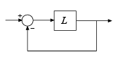
S = allmargin(L)L. The negative feedback loop is computed as
feedback(L,eye(M)), where M is the number
of inputs and outputs in L.
For a MIMO system, allmargin returns loop-at-a-time stability
margins for the negative-feedback closed loop system. Use
allmargin to find classical margins of any SISO or MIMO
model, including models with delays.
S = allmargin(L,Focus=[fmin,fmax])fmin,fmax], ignoring stability issues
outside this range. For instance, use this syntax to ignore very low frequency
dynamics for the purpose of computing stability margins. (since R2024a)
Examples
Input Arguments
Open-loop response, specified as a dynamic system model.
L can be SISO or MIMO, as long as it has the same
number of inputs and outputs. allmargin computes the
classical stability margins for the negative-feedback closed-loop system
feedback(L,eye(M)):
To compute the stability margins of the positive feedback system
feedback(L,eye(M),+1), use
allmargin(-L).
When you have a controller P and a plant
C, you can compute the stability margins for gain and
phase variations at the plant inputs or outputs. From the following
diagram:
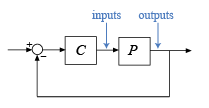
To compute margins at the plant outputs, set
L = P*C.To compute margins at the plant inputs, set
L =
                                    C*P
.
L can be continuous time or discrete time. If
L is a generalized state-space model
(genss or uss), then
allmargin uses the current or nominal value of all
control design blocks in L.
If L is a frequency-response data model (such as
frd), then allmargin computes
the margins at each frequency represented in the model. The function returns
the margins at the frequency with the smallest stability margin.
If L is a model array, then
allmargin computes margins for each model in the
array.
Since R2024a
Frequency range to consider in stability analysis, specified as a
two-element vector containing the lower and upper limits of the range. The
margin computation ignores dynamics outside this range. Specify frequencies
in rad/TimeUnit, where TimeUnit is the
TimeUnit property of the input dynamic system.
Example: [1e-3,1e6]
Magnitude of the system response in absolute units, specified as a 3-D
array. mag is an M-by-M-by-N array, where M is the
number of inputs or outputs, and N is the number of frequency points. For
more information on obtaining mag, see Obtain Magnitude and Phase Data and Magnitude and Phase of MIMO System.
Phase of the system response in degrees, specified as a 3-D array.
phase is an M-by-M-by-N array, where M is the
number of inputs or outputs, and N is the number of frequency points. For
more information on obtaining phase, see Obtain Magnitude and Phase Data and Magnitude and Phase of MIMO System.
Frequencies at which the magnitude and phase values of system response are
obtained, specified as a column vector. You can provide the frequency vector
w in any units; allmargin returns
frequencies in the same units. allmargin interpolates
between frequency points to approximate the true stability margins.
Sample time, specified as an integer. allmargin uses
ts to find the stability margins from frequency
response data.
For continuous-time models, set
ts = 0.For discrete-time models,
tsis a positive integer representing the sampling period. To denote a discrete-time model with unspecified sample time, setts = -1.
Output Arguments
Tips
allmarginassumes that the system with open-loop responseLis a negative-feedback system. To compute the classical stability margins of the positive feedback systemfeedback(L,eye(M),+1), useallmargin(-L).To compute classical margins for a system modeled in Simulink®, first linearize the model to obtain the open-loop response at a particular operating point. Then, use
allmarginto compute classical stability margins for the linearized system. For more information, see Stability Margins of a Simulink Model (Robust Control Toolbox).If you have Robust Control Toolbox™ software, you can use
diskmargin(Robust Control Toolbox) to compute disk-based margins that define a range of "safe" gain and phase variations for which the feedback loop remains stable.
Version History
Introduced before R2006aSee Also
Linear System Analyzer | margin | diskmargin (Robust Control Toolbox)
Topics
- Stability Margins of a Simulink Model (Robust Control Toolbox)