OQPSK Demodulator Baseband
Demodulation using OQPSK method
Libraries:
Communications Toolbox /
Modulation /
Digital Baseband Modulation /
PSK
Description
The OQPSK Demodulator Baseband block applies pulse shape filtering to the input waveform and demodulates it using the offset quadrature phase shift keying (OQPSK) method. For more information, see Pulse Shaping Filter. The input is a baseband representation of the modulated signal.
For information about delays incurred by modulator-demodulator pair processing, see Modulation Delays.
Examples
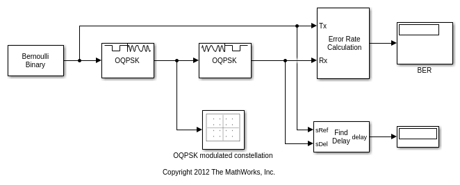
This example shows the OQPSK Modulator Baseband and OQPSK Demodulator Baseband blocks connected with no channel or impairments distorting the signal between them. They are configured for frame-based processing with bit signal inputs.
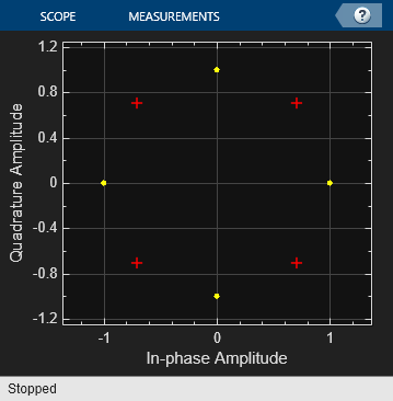
The cm_ex_oqpsk_mod_demod_pair model displays the constellation of the OQPSK-modulated signal and computes the bit error rate of the recovered signal. The delay of the recovered signal, as determined by the Find Delay block, is applied in the Error Rate Calculation block. For perfect data recovery, the bit error rate is zero.
The model contains no channel or RF impairments, so the constellation diagram plot shows an unimpaired constellation.
This example shows the OQPSK Demodulator Baseband block configured for single-rate processing using integer or bit for the input type.
Use the Open model button to open the slex_oqpskdemod_framebased model.

In single-rate processing mode, the input and output signals have the same port sample time. The block implicitly implements the rate change by making a size change at the output when compared to the input. In this mode, the input column vector length must be an integer multiple of the Samples per symbol parameter.
When you set the Output type parameter to
Integer, the output width is the number of input symbols.When you set Output type parameter to
Bit, the output width is two times the number of input symbols.
This example shows the OQPSK Demodulator Baseband block configured for multirate processing using integer or bit for the input type.
Use the Open model button to open the cm_ex_oqpskdemod_samplebased model.

In multirate processing mode, the input and output signals have different port sample times. In this mode, the output symbol time is Samples per symbol times the input sample time.
When you set the Output type parameter to
Integer, the output is a scalar value from0to3.When you set Output type parameter to
Bit, the output width is two.
The OQPSK demodulation in the doc_oqpsk_modulation_delay model causes the demodulated signal to lag, compared to the unmodulated signal. When computing error statistics, the model must adjust the Receive delay parameter in the Error Rate Calculation block to account for the demodulation delay. With the incorrect delay setting, the computed error rate is incorrect and significantly higher than expected.
Explore the model

The Random Integer Generator block has the Set size parameter set to 4 to generate integer in the range [0,3] for OQPSK modulation. The OQPSK Modulator Baseband and OQPSK Demodulator Baseband blocks are configured with a custom filter pulse shape that has filter numerator set to [0.7071 0.7071], samples per symbol set to 2, and the Rate options parameter set to Allow multirate processing. The AWGN Channel block has the Es/N0 set to 6 dB. The Error Rate Calculation block begins error rate computation with the first received sample and sends the results an output port. The Display block is resized to show the output triplet (error rate, number of errors, and number of samples). The Simulation tab has the Stop time set to 1000.
After running the simulation the display block shows error rate calculations and the To Workspace block outputs the yout variable with error rate calculations for all frames. The error rate varies depending on the initial seed value in the Random Integer Generator block.
Run the simulation
Run the simulation with the receive delay set to 0 in the Error Rate Calculation block. Display the computed error rate. The computed error rate is higher than expected.
Calculated error rate = 0.765235
Change the receive delay set to 1 in the Error Rate Calculation block. Rerun the simulation and display the computed error rate. The computed error rate is in line with the expected value for an OQPSK signal transmission through an AWGN channel with Es/N0 set to 6 dB.
Calculated error rate = 0.036000
This example shows how to create an end-to-end communication system using OQPSK modulator and demodulator block using Butterworth pulses, custom pulse shape and an AWGN channel. This model also calculates the bit error rate between the transmitter and the receiver.
Use the Open model button to open the cm_ex_oqpskmoddemod_iir model.

In this communication system, to receive the IIR pulses the demodulator is in the Integrate and Dump mode. For this, set the Pulse Shape property to Custom and FilterNumerator to 1.
Ports
Input
Input baseband waveform, specified as a discrete-time complex scalar or column vector.
The block processes the input signal based on the Output type setting.
Data Types: double
Complex Number Support: Yes
Output
Output data, returned as an integer or bit column vector.
Parameters
To edit block parameters interactively, use the Property Inspector. From the Simulink® Toolstrip, on the Simulation tab, in the Prepare gallery, select Property Inspector.
Modulation
Output type, specified as Integer or
Bit.
When you set Output type to
Integer, the block outputs a vector of integer symbols with values from 0 to 3, the length of which is the number of output symbols.When you set Output type to
Bit, the block outputs a 2-bit binary representation of integers, in a binary-valued, even-length vector.
The input period for each integer or bit pair is the Samples per symbol times the output sample period.
Phase offset from π/4, specified as a scalar in radians. The phase offset is applied to the zeroth point of the signal constellation before delay of quadrature component. After the OQPSK imaginary-component delay the signal is normalized with unity power.
Example: Setting Phase offset (rad) to
pi/4 aligns the zeroth point of the QPSK signal
constellation point on the axes, {(1,0), (0,j), (-1,0),
(0,-j)}.
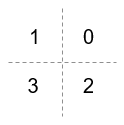
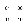
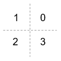
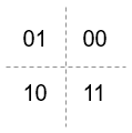
Signal constellation bit mapping, specified as
Gray, Binary,
or a custom 4-element numeric vector of integers with values from 0 to
3.
| Setting | Constellation Mapping for Integers | Constellation Mapping for Bits | Comment |
|---|---|---|---|
|
|
| The signal constellation mapping is Gray-encoded. |
|
|
| The signal constellation mapping for the input integer
|
Custom 4-element numeric vector of integers with values from 0 to 3 |
|
| Elements [a b c d] must be composed of the set of values [0, 1, 2, 3] in any order. |
Filtering
Select the filtering pulse shape: Half
sine, Normal raised cosine,
Root raised cosine, or
Custom.
Raised cosine filter rolloff factor, specified as a scalar from
0 to 1.
Dependencies
This property is enabled when Pulse shape is Normal raised
cosine or Root raised
cosine.
Filter length in symbols, specified as a scalar. An ideal raised cosine filter has an infinite impulse response. However, to realize a practical implementation of this filter, the object truncates the impulse response to Filter span (in symbols) symbols.
Dependencies
This property is enabled when Pulse shape is Normal raised
cosine or Root raised
cosine.
FIR filter numerator, specified as a row vector.
Dependencies
This parameter is enabled when Pulse shape is Custom.
Number of samples per symbol, specified as a positive even integer.
Other Parameters
Enforce single-rate processing— Executes the model, ensuring that the input and output signals have the same port sample time. The block implements the rate change by making a size change at the output when compared to the input. For integer outputs, the output width equals 1/Samples per symbol times the input width.For an example, see Single-Rate Processing with OQPSK Demodulator Block.
Allow multirate processing— Executes the model, allowing the input and output signals to have different port sample times. The output symbol time is Samples per symbol times the input sample time.For an example, see Multirate Processing with OQPSK Demodulator Block.
Select the output data type: double,
single, or
uint8.
Block Characteristics
Data Types |
|
Multidimensional Signals |
|
Variable-Size Signals |
|
More About
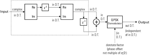
Every Samples per symbol input samples produce one output symbol. In this figure, the dotted line represents the region comprising the input sample processing.
Digital modulation and demodulation blocks incur delays between their inputs and outputs that result in an offset in the arrival time of the received data. Data that enters a modulation or demodulation block at time T appears in the output at time T+delay. Take system delays into account when comparing transmitted data with received data, such as in overlaid plots or when computing error statistics. As shown here, the OQPSK modulation-demodulation delay varies depending on the pulse shaping filter, input/output data setting, and simulation configuration.
| Pulse Shape | Rate Options | Treat Each Discrete Rate as a Separate Task? | Input/Output Data (*) | End-to-End Delay Incurred by an OQPSK Modulator-Demodulator Block Pair (in samples) |
|---|---|---|---|---|
Half sine or
Custom | Enforce single-rate
operation | N/A | Integer | 1 |
Bit | 2 | |||
Allow multirate
processing | false (single tasking) | Integer | length(data) + 1 + 1 | |
Bit | length(data) + 2 + 2 | |||
true (multitasking) | Integer | length(data) + 1 + 2 | ||
Bit | length(data) + 2 + 4 | |||
Normal raised
                                    cosine
or
Root raised cosine | Enforce single-rate
operation | N/A | Integer | Filter span (in symbols) |
Bit | 2*Filter span (in symbols) | |||
Allow multirate
processing | false (single tasking) | Integer | length(data) + Filter span (in symbols) + 1 | |
Bit | length(data) + 2*Filter span (in symbols) + 2 | |||
true (multitasking) | Integer | 2*length(data) + Filter span (in symbols) + 2 | ||
Bit | 2*length(data) + 2*Filter span (in symbols) + 4 | |||
(*) The data type parameter is Input type for modulation and Output type for demodulation. | ||||
The OQPSK modulation scheme requires oversampling of two or greater in order to delay (or offset) the quadrature channel by 90 degrees. This oversampling is achieved through interpolation filtering implemented by pulse shaping.
Extended Capabilities
C/C++ Code Generation
Generate C and C++ code using Simulink® Coder™.
Version History
Introduced before R2006a
See Also
Blocks
Objects
Topics
MATLAB Command
You clicked a link that corresponds to this MATLAB command:
Run the command by entering it in the MATLAB Command Window. Web browsers do not support MATLAB commands.
웹사이트 선택
번역된 콘텐츠를 보고 지역별 이벤트와 혜택을 살펴보려면 웹사이트를 선택하십시오. 현재 계신 지역에 따라 다음 웹사이트를 권장합니다:
또한 다음 목록에서 웹사이트를 선택하실 수도 있습니다.
사이트 성능 최적화 방법
최고의 사이트 성능을 위해 중국 사이트(중국어 또는 영어)를 선택하십시오. 현재 계신 지역에서는 다른 국가의 MathWorks 사이트 방문이 최적화되지 않았습니다.
미주
- América Latina (Español)
- Canada (English)
- United States (English)
유럽
- Belgium (English)
- Denmark (English)
- Deutschland (Deutsch)
- España (Español)
- Finland (English)
- France (Français)
- Ireland (English)
- Italia (Italiano)
- Luxembourg (English)
- Netherlands (English)
- Norway (English)
- Österreich (Deutsch)
- Portugal (English)
- Sweden (English)
- Switzerland
- United Kingdom (English)
