M-PAM Demodulator Baseband
Demodulate PAM-modulated data
Library
AM, in Digital Baseband sublibrary of Modulation
Description
The M-PAM Demodulator Baseband block demodulates a signal that was modulated using M-ary pulse amplitude modulation. The input is a baseband representation of the modulated signal.
The signal constellation has M points, where M is the M-ary number parameter. M must be an even integer. The block scales the signal constellation based on how you set the Normalization method parameter. For details on the constellation and its scaling, see the reference page for the M-PAM Modulator Baseband block.
This block accepts a scalar or column vector input signal. For information about the data types each block port supports, see Supported Data Types.
Note
All values of power assume a nominal impedance of 1 ohm.
Integer-Valued Signals and Binary-Valued Signals
When you set the Output type parameter
to Integer
, the block outputs integer values
between 0
and M-1
. M represents
the M-ary number block parameter.
When you set the Output type parameter
to Bit
, the block outputs binary-valued
signals that represent integers. The block represents each integer
using a group of K = log2(M)
bits, where K represents the number of bits per
symbol. The output vector length must be an integer multiple of K.
The Constellation ordering parameter indicates how the block assigns binary words to points of the signal constellation. More details are on the reference page for the M-PAM Modulator Baseband block.
Algorithm
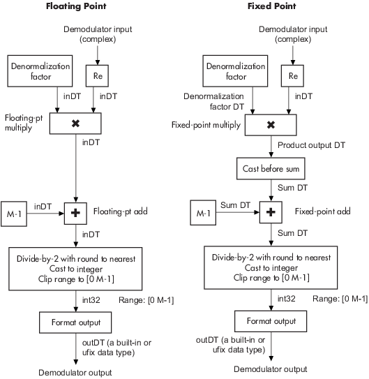
The demodulator algorithm maps received input signal constellation values to M-ary integer symbol indices between 0 and M-1 and then maps these demodulated symbol indices to formatted output values.
The integer symbol index computation is performed by first scaling the real part of the input signal constellation (possibly with noise) by a denormalization factor derived from the Normalization method and related parameters. This denormalized value is added to M-1 to translate it into an approximate range between 0 and 2 x (M-1) plus noise. The resulting value is then rescaled via a divide-by-two (or, equivalently, a right-shift by one bit for fixed-point operation) to obtain a range approximately between 0 and M-1 (plus noise). The noisy index value is rounded to the nearest integer and clipped, via saturation, to the exact range of [0 M-1]. Finally, based on other block parameters, the integer index is mapped to a symbol value that is formatted and cast to the selected Output data type.
The following figures contains signal flow diagrams for floating-point and fixed-point
algorithm operation. The floating-point diagrams apply when the input signal data type
is double
or single
. The fixed-point diagrams
apply when the input signal is a signed fixed-point data type. Note that the diagram is
simplified when using normalized constellations (i.e., denormalization factor is
1).
Signal-Flow Diagrams with Denormalization Factor Equal to 1
Signal-Flow Diagrams with Nonunity Denormalization Factor
Parameters
- M-ary number
The number of points in the signal constellation. It must be an even integer.
- Output type
Determines whether the output consists of integers or groups of bits. If this parameter is set to
Bit
, then the M-ary number parameter must be 2K for some positive integer K.- Constellation ordering
Determines how the block maps each integer to a group of output bits.
- Normalization method
Determines how the block scales the signal constellation. Choices are
Min. distance between symbols
,Average Power
, andPeak Power
.- Minimum distance
The distance between two nearest constellation points. This field appears only when Normalization method is set to
Min. distance between symbols
.- Average power, referenced to 1 ohm (watts)
The average power of the symbols in the constellation, referenced to 1 ohm. This field appears only when Normalization method is set to
Average Power
.- Peak power, referenced to 1 ohm (watts)
The maximum power of the symbols in the constellation, referenced to 1 ohm. This field appears only when Normalization method is set to
Peak Power
.
- Output
When the parameter is set to
'Inherit via internal rule'
(default setting), the block will inherit the output data type from the input port. The output data type will be the same as the input data type if the input is of typesingle
ordouble
. Otherwise, the output data type will be as if this parameter is set to'Smallest unsigned integer'
.When the parameter is set to
'Smallest unsigned integer'
, the output data type is selected based on the settings used in the Hardware Implementation pane of the Configuration Parameters dialog box of the model. IfASIC/FPGA
is selected in the Hardware Implementation pane, the output data type is the ideal minimum size, i.e.,ufix(1)
for bit outputs, andufix(ceil(log2(M)))
for integer outputs. For all other selections, it is an unsigned integer with the smallest available word length large enough to fit the ideal minimum size, usually corresponding to the size of a char (e.g.,uint8
).For integer outputs, this parameter can be set to
Smallest unsigned integer
,int8
,uint8
,int16
,uint16
,int32
,uint32
,single
, anddouble
. For bit outputs, the options areSmallest unsigned integer
,int8
,uint8
,int16
,uint16
,int32
,uint32
,boolean
,single
, ordouble
.- Denormalization factor
This parameter applies when a fixed-point input is not normalized. It can be set to
Same word length as input
orSpecify word length
, in which case a field is enabled for user input. A best-precision fraction length is always used.- Product output
This parameter only applies when the input is a fixed-point signal and there is a nonunity (not equal to 1) denormalized factor. It can be set to
Inherit via internal rule
orSpecify word length
, which enables a field for user input.Setting to
Inherit via internal rule
computes the full-precision product word length and fraction length. Internal Rule for Product Data Types in DSP System Toolbox™ User's Guide describes the full-precision Product output internal rule.Setting to
Specify word length
allows you to define the word length. The block computes a best-precision fraction length based on the word length specified and the pre-computed worst-case (min/max) real world value Product output result. The worst-case Product output result is precomputed by multiplying the denormalized factor with the worst-case (min/max) input signal range, purely based on the input signal data type.The block uses the Rounding method when the result of a fixed-point calculation does not map exactly to a number representable by the data type and scaling storing the result. For more information, see Rounding Modes or Rounding Mode: Simplest (Fixed-Point Designer).
- Sum
This parameter only applies when the input is a fixed-point signal. It can be set to
Inherit via internal rule
,Same as product output
, orSpecify word length
, in which case a field is enabled for user inputSetting
Inherit via internal rule
computes the full-precision sum word length and fraction length, based on the two inputs to the Sum in the fixed-point Hard Decision Algorithm signal flow diagram. The rule is the same as the fixed-point inherit rule of the internal Accumulator data type parameter in the Simulink® Sum (Simulink) block.Setting
Specify word length
allows you to define the word length. A best precision fraction length is computed based on the word length specified in the pre-computed maximum range necessary for the demodulated algorithm to produce accurate results. The signed fixed-point data type that has the best precision fully contains the values in the range 2 * (M-1) for the specified word length.Setting to
Same as product output
allows the Sum data type to be the same as the Product output data type (when Product output is used). If the Product output is not used, then this setting will be ignored and theInherit via internal rule
Sum setting will be used.
Supported Data Types
Port | Supported Data Types |
---|---|
Input |
|
Output |
|
Pair Block
Extended Capabilities
Version History
Introduced before R2006a