M-PAM Modulator Baseband
Modulate using M-ary pulse amplitude modulation
Libraries:
Communications Toolbox /
Modulation /
Digital Baseband Modulation /
AM
Description
The M-PAM Modulator Baseband block modulates a signal by using M-ary pulse amplitude modulation. The output is a baseband representation of the modulated signal.
Note
All values of power assume a nominal impedance of 1 ohm.
Examples
The doc_pam_mod model uses the M-PAM Modulator Baseband block to modulate input data. Observe changes in the constellation size and scaling for various normalization methods and modulation orders.
A Random Integer Generator block generates a vector of integers over the range [0, M-1] as input for a modulator that applies M-PAM.

Update mask parameters in the M-PAM Modulator Baseband block. Set the modulation order to 8 and the default minimum distance between symbols normalization method. Click the View Constellation parameter on the M-PAM Modulator Baseband block mask to observe the constellation.

Update the M-PAM Modulator Baseband block mask to set the average power normalization method. Click the View Constellation parameter on the M-PAM Modulator Baseband block mask to observe the change in the constellation scaling.

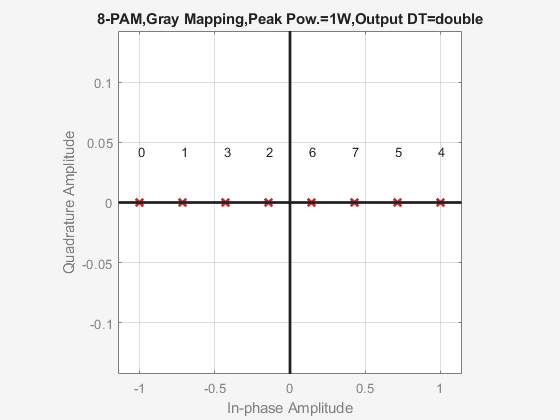
Update the M-PAM Modulator Baseband block mask to set the peak power normalization method. Click the View Constellation parameter on the M-PAM Modulator Baseband block mask to observe the change in the constellation scaling.
Update the M-PAM Modulator Baseband block mask to set the modulation order to 4. Click the View Constellation parameter on the M-PAM Modulator Baseband block mask to observe the constellation.

Update the M-PAM Modulator Baseband block mask to set the modulation order to 2. Click the View Constellation parameter on the M-PAM Modulator Baseband block mask to observe the constellation.

Ports
Input
Output
Parameters
Block Characteristics
More About
The Data Type Assistant helps you set data
attributes. To use the Data Type Assistant, click ![]() . For more information, see Specify Data Types Using Data Type Assistant (Simulink).
. For more information, see Specify Data Types Using Data Type Assistant (Simulink).
Algorithms
Extended Capabilities
Version History
Introduced before R2006a