Getting Started with Powertrain Blockset
The Powertrain Blockset™ provides reference application projects assembled from blocks and subsystems. Use the reference applications as a starting point to create your own powertrain models.
| Objective | For | See |
|---|---|---|
Design tradeoff analysis and component sizing, control parameter optimization, or hardware-in-the-loop (HIL) testing. | Full conventional vehicle with spark-ignition (SI) or combustion-ignition (CI) | |
Hybrid electric vehicle (HEV) — Multimode | Build Hybrid Electric Vehicle Multimode Model | |
HEV — Input power-split | Build Hybrid Electric Vehicle Input Power-Split Model | |
Full electric vehicle | Build Full Electric Vehicle Model | |
Engine and controller calibration, validation, and optimization before integration with the vehicle model. | CI engine plant and controller | Calibrate, Validate, and Optimize CI Engine with Dynamometer Test Harness |
SI engine plant and controller | Calibrate, Validate, and Optimize SI Engine with Dynamometer Test Harness |
This example shows how to run the conventional vehicle reference application and examine the final drive gear ratio impact on fuel economy and tailpipe emissions.
Running this example requires a Stateflow® license. You can install a Stateflow trial license using the Add-On Explorer.
Open the conventional vehicle reference application project. By default, the application has a 1.5–L spark-ignition (SI) engine and a final drive gear ratio of
Project files open in a writable location.3.Enable data logging for the fuel economy and tailpipe emissions signals.
Open the
Visualizationsubsystem. Select theUS Fuel Economy MPGesignal line andEnable Data Logging.
In the
Visualizationsubsystem, enable data logging on the tailpipe emissions signals.
Save the model.
View the final drive gear ratio for the conventional vehicle.
In the
Vehiclesubsystem, navigate to theConfiguredSimulinkPlantModel>Front Axlesubsystem.
Open the
Front Axlesubsystem and navigate to theOpen DifferentialSubsystem. Open the Open Differential block.In the Open Differential block mask, the Carrier to driveshaft ratio, Ndiff parameter represents the final drive gear ratio.

In the Model Explorer, confirm the
PlntDiffrntlRatioparameter value. The conventional vehicle project stores parameter values in a data dictionary. The parameterized valuePlntDiffrntlRatiois set to3.32.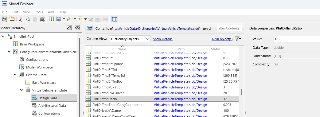
Run a conventional vehicle simulation with a final drive gear ratio of
3.32. Import the results to the Simulation Data Inspector.In the
ConfiguredConventionalVirtualVehiclemodel, run the simulation for the default run time. The simulation can take time to run. View progress in the Simulink® window.On the Simulink Editor toolbar, click the Data Inspector button
 to open the Simulation Data
Inspector.
to open the Simulation Data
Inspector.In the Simulation Data Inspector, select Import. In the Import dialog box, accept the defaults and select Import.

In the results field for the run, right-click to rename the run
DiffRatio=3.32.
Run a conventional vehicle simulation with a final drive gear ratio of
2.5. Import the results to the Simulation Data Inspector.In the Model Explorer, set the
PlntDiffrntlRatioparameter value to2.5.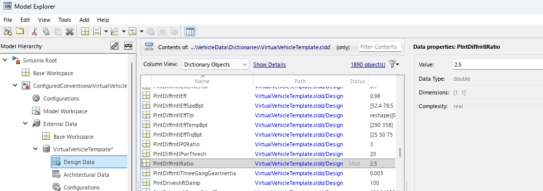
Save the model.
In the
ConfiguredConventionalVirtualVehiclemodel, run the simulation for the default run time. The simulation can take time to run. View progress in the Simulink window.On the Simulink Editor toolbar, click the Data Inspector button
to open the Simulation Data
Inspector.In the Simulation Data Inspector, select Import. In the Import dialog box, accept the defaults and select Import.
In the results field for the run, right-click to rename the run
DiffRatio=2.5.
Use the Simulation Data Inspector to explore the results. To assess the impact of the final drive gear ratio on the fuel economy and tailpipe emissions, view the plots of the simulation results. For example, these simulation results indicate a better powertrain match when the final drive gear ratio is
2.5:Fuel economy increases when the final drive gear ratio changes from
3.32to2.5.Tailpipe hydrocarbon (HC) mass emissions decrease when the final drive gear ratio changes from
3.32to2.5.

Next Steps
Assess the impact of the final drive gear ratio on vehicle performance. Although the fuel economy and tailpipe emissions indicate a better powertrain match when the final drive gear ratio is 2.5, the ratio also impacts performance.
To assess the vehicle performance, examine 0 to 100 km/hr acceleration times for each axle setting. You can use the Drive Cycle Source block to output a constant velocity of (100/3.6) m/s.