Prepare Custom Aircraft Mesh for the Unreal Editor
This example shows you how to create an aircraft mesh that is compatible with the project in the Aerospace Blockset™ Interface for Unreal Engine® Projects support package. For illustration purposes, it uses Blender®.You can specify the mesh in the Simulation 3D Aircraft block to visualize the aircraft in the Unreal® Editor when you run a simulation.
Before you start, install the Aerospace Blockset Interface for Unreal Engine Projects support package. See Customize 3D Scenes for Aerospace Blockset Simulations.
To create a compatible custom aircraft mesh, follow these workflow steps.
Step | Description | |
|---|---|---|
| Step 1: Check Units and Axes | In a 3-D creation environment, set up the units and axes for the mesh. | |
Set up the aircraft mesh bone hierarchy and specify part names. | ||
| Step 3: Connect Mesh to Skeleton | Parent the entire mesh to the armature. | |
| Step 4: Assign Materials | Optionally, assign materials to the aircraft parts. | |
| Step 5: Export Mesh and Armature | Export the aircraft mesh and armature in . | |
| Step 6: Import Mesh to Unreal Editor | Import the aircraft mesh into the Unreal Editor. | |
| Step 7: Set Block Parameters | Set up the block parameters. | |
Note
To create the mesh, this example uses the 3-D creation software Blender Version 2.93.
Step 1: Check Units and Axes
Create or import an aircraft mesh into a 3-D modeling tool, for example, Blender.
Check that the Length unit is set to
Centimetersand the Rotation unit is set toDegrees.If the units are not correctly set, then correct them. For example, in Blender, use steps like these:
Change Unit scale from
1.0to0.01, and Length fromMeterstoCentimeters.Check the dimensions of some mesh objects.
Units should be centimeters and the sizes should be 100 times too small.
Select the entire mesh and scale it by 100 in all three dimensions.
Position the mesh so that the global axes origin is near the center of mass, with X pointing forward and Z pointing upward.
To complete the transformation, click Object > Apply > Location and Object > Apply > Scale.
Step 2: Set Up Bone Hierarchy
Create an armature, if necessary, and use the following naming convention for the bones to ensure compatibility with the animation components in the support package. Make sure to follow the bone hierarchy shown.
Note
You can omit or add bones and still maintain compatibility with the custom aircraft skeleton in the support package, as long as the rules for sharing skeleton assets are met.
Most bones share the vertical, global-z-axis-aligned orientation of the root bone.
Align wheel bones with the global y-axis.
Align a control surface (such as an aileron) bone perpendicular to its surface and rotate it to align with the surface hinge line.
Check that no mesh elements have the same names as any of the bones. Rename them as necessary.

Step 3: Connect Mesh to Skeleton
Parent the entire mesh to the armature, for example, Blender, in Object Mode:
Select the entire mesh.
Click Shift+Left on one of the bones in the viewport.
To display the parenting menu, press Ctrl+P, and choose Armature Deform with Empty Groups to create an empty mesh Vertex Group for every bone.
For each mesh object:
Assign weight to the appropriate Vertex Group.
Add an
Armaturemodifier for that Vertex Group.
Step 4: Assign Materials
Optionally, assign material slots to the aircraft parts. The first material slot should correspond to the aircraft body. The Simulation 3D Aircraft block sets only the first slot material (i.e. color) assignment.
Step 5: Export Mesh and Armature
Export the mesh and armature in the .fbx file format, for example, in
Blender:
On the Object Types pane, select Armature and Mesh.
On the Transform pane, set:
Scale to 1.00
Apply Scalings to
All
                Local
Forward to
X ForwardUp to
Z Up
Select Apply Unit.
Select Use Space Transform.
On the Geometry pane:
Set Smoothing to
Face.Select Apply Modifiers.
On the Armature pane, set:
Primary Bone Axis to
Z Axis.Secondary Bone Axis to
X Axis.Armature FBXNode Type to
Null.
Clear Bake Animation, then select Export FBX.
Step 6: Import Mesh to Unreal Editor
Open the Unreal Engine
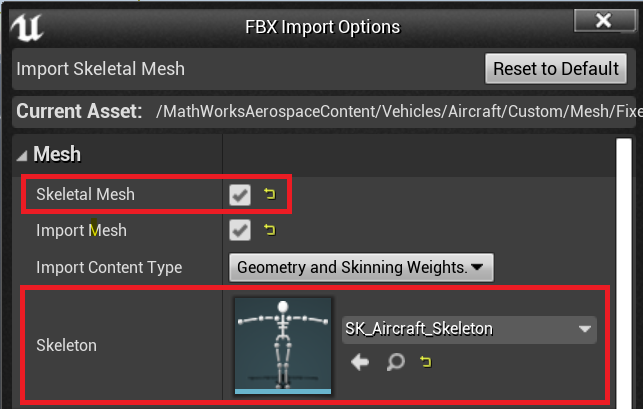
AutoVrtlEnv.uprojectproject in the Unreal Engine Editor.In the editor, import the FBX® file as a skeletal mesh. Assign the Skeleton to the
SK_Aircraft_Skeletonasset.
Note
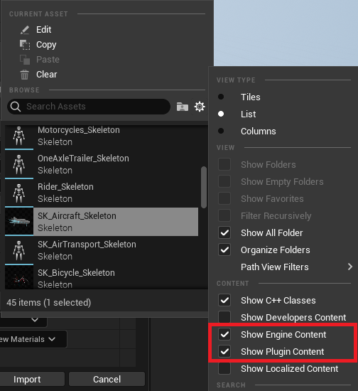
If you cannot select
SK_Aircraft_Skeleton, click the gearbox. Make sure Show Engine Content and Show Plugin Content are both selected.
Open the imported mesh and assign materials to each material slot.
Step 7: Set Block Parameters
In your Simulink® model, set these Simulation 3D Aircraft block parameters:
Type to
Custom.Path to the path in the Unreal Engine project that contains the imported mesh. For example, if a mesh named SK_X15 is imported into the
Vehicles/Aircraft/Custom/Meshfolder, then the full path is/MathWorksAerospaceContent/Vehicles/Aircraft/Custom/Mesh/SK_X15.SK_X15.
See Also
Simulation 3D Scene Configuration | Simulation 3D Aircraft
Topics
- How 3D Simulation for Aerospace Blockset Works
- Unreal Engine Simulation Environment Requirements and Limitations