NR PDSCH Resource Allocation and DM-RS and PT-RS Reference Signals
This example shows the time-frequency aspects of the new radio (NR) physical downlink shared channel (PDSCH), the associated demodulation reference signal (DM-RS), and phase tracking reference signal (PT-RS). The example shows how PDSCH resource allocation affects the time-frequency structure of DM-RS and PT-RS.
Introduction
In 5G NR, PDSCH is the physical downlink channel that carries user data. DM-RS and PT-RS are the reference signals associated with PDSCH. These signals are generated within the PDSCH allocation, as defined in TS 38.211 Sections 7.4.1.1 and 7.4.1.2 [1]. DM-RS is used for channel estimation as part of coherent demodulation of PDSCH. To compensate for the common phase error (CPE), 3GPP 5G NR introduced PT-RS. Phase noise produced in local oscillators introduces a significant degradation at mmWave frequencies. It produces CPE and inter-carrier interference (ICI). CPE leads to an identical rotation of a received symbol in each subcarrier. ICI leads to loss of orthogonality between the subcarriers. PT-RS is used mainly to estimate and minimize the effect of CPE on system performance.
The 5G Toolbox™ provides the functions for physical (PHY) layer modeling with varying levels of granularity. The levels of granularity range from PHY channel level functions that perform the transport and physical channel processing to individual channel processing stage functions performing cyclic redundancy check (CRC) coding, code block segmentation, low density parity check (LDPC) channel coding, and so on. The toolbox offers the reference signals functionality associated with the PDSCH as functions nrPDSCHDMRS, nrPDSCHDMRSIndices, nrPDSCHPTRS, and nrPDSCHPTRSIndices.
PDSCH
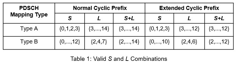
PDSCH is the physical channel that carries the user data. The resources allocated for PDSCH are within the bandwidth part (BWP) of the carrier, as defined in TS 38.214 Section 5.1.2 [2]. The resources in the time domain for PDSCH transmission are scheduled by downlink control information (DCI) in the field Time domain resource assignment. This field indicates the slot offset , starting symbol S, the allocation length L, and the mapping type of PDSCH. The valid combinations of S and L are shown in Table 1. For mapping type A, value of S is 3 only when the DM-RS type A position is set to 3.
The resources in the frequency domain for PDSCH transmission are scheduled by a DCI in the field Frequency domain resource assignment. This field indicates whether the resource allocation of resource blocks (RBs) is contiguous or noncontiguous, based on the allocation type. The RBs allocated are within the BWP.
The 5G Toolbox™ provides the nrCarrierConfig and nrPDSCHConfig objects to set the parameters related to the PDSCH within the BWP.
% Setup the carrier with 15 kHz subcarrier spacing and 10 MHz bandwidth
carrier = nrCarrierConfig;
carrier.SubcarrierSpacing = 15;
carrier.CyclicPrefix = 'normal';
carrier.NSizeGrid = 52;
carrier.NStartGrid = 0;

% Configure the physical downlink shared channel parameters
pdsch = nrPDSCHConfig;
pdsch.NSizeBWP = [];   % Empty implies that the value is equal to NSizeGrid
pdsch.NStartBWP = [];  % Empty implies that the value is equal to NStartGrid
pdsch.PRBSet = 0:51;   % Allocate the complete carrier
pdsch.SymbolAllocation = [0 14]; % Symbol allocation [S L]
pdsch.MappingType = 'A'; % PDSCH mapping type ('A' or 'B')
DM-RS
DM-RS is used to estimate the radio channel. The signal is present only in the RBs allocated for the PDSCH. The DM-RS structure is designed to support different deployment scenarios and use cases. A front-loaded design supports low-latency transmissions, twelve orthogonal antenna ports for MIMO transmissions, and up to four reference signal transmission instances in a slot to support high-speed scenarios. The front-loaded reference signals indicate that the signal occurs early in the transmission. The DM-RS is present in each RB allocated for PDSCH.
Parameters That Control Time Domain Resources
The parameters that control DM-RS OFDM symbol locations are:
PDSCH symbol allocation
Mapping type
DM-RS type A position
DM-RS length
DM-RS additional position
The symbol allocation of PDSCH indicates the OFDM symbol locations used by the PDSCH transmission in a slot. DM-RS symbol locations lie within the PDSCH symbol allocation. The positions of DM-RS OFDM symbols depend on the mapping type. The mapping type of PDSCH is either slot-wise (type A) or non-slot-wise (type B). The positions of any additional DM-RS symbols are defined by a set of tables, as specified in TS 38.211 Section 7.4.1.1.2 [1]. For the purpose of indexing the tables, the specification defines the term indicating the duration of OFDM symbols to be accounted for, depending on the mapping type.
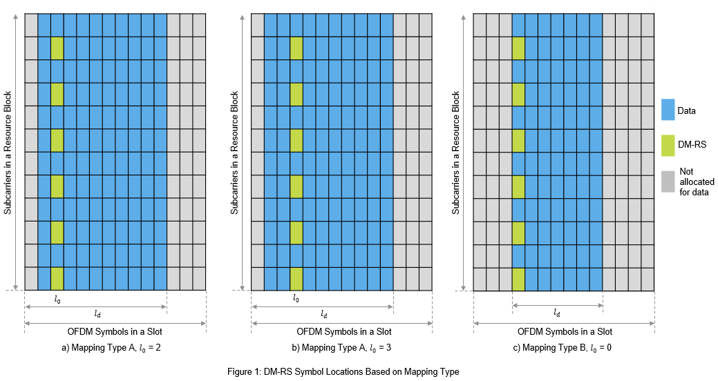
For mapping type A, the DM-RS OFDM symbol locations are defined relative to the first OFDM symbol of the slot (symbol #0). The location of first DM-RS OFDM symbol () is provided by the DM-RS type A position, which is either 2 or 3. For any additional DM-RS, the duration of OFDM symbols () is the number of OFDM symbols between the first OFDM symbol of the slot (symbol #0) and the last OFDM symbol of the allocated PDSCH resources. Note that may differ from the number of OFDM symbols allocated for PDSCH, when the first OFDM symbol of PDSCH is other than symbol #0.
For mapping type B, the DM-RS OFDM symbol locations are defined relative to the first OFDM symbol of allocated PDSCH resources. The location of first DM-RS OFDM symbol () is always 0, meaning that the first DM-RS OFDM symbol location is the first OFDM symbol location of the allocated PDSCH resources. For any additional DM-RS, the duration of OFDM symbols () is the duration of the allocated PDSCH resources.
Figure 1 illustrates the DM-RS symbol locations depending on the mapping type for an RB within a slot, having single-symbol DM-RS. The figure shows a configuration with PDSCH occupying the OFDM symbols from 1 to 10 (0-based) with equal to 11 for mapping type A, and from 3 to 9 (0-based) with equal to 7 for mapping type B respectively.
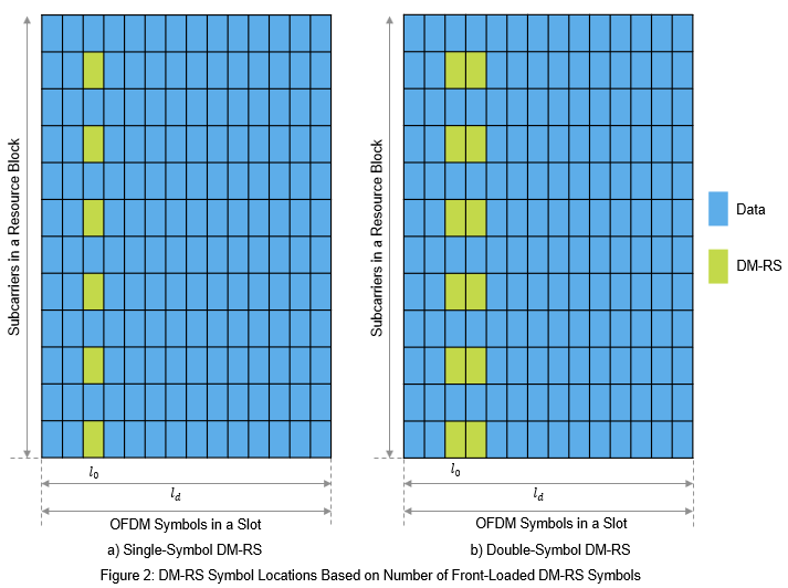
The maximum number of DM-RS OFDM symbols used by a UE is configured by RRC signaling (dmrs-AdditionalPosition and maxLength). The maxLength RRC parameter configures the length of DM-RS symbol, single symbol DM-RS or double symbol DM-RS. For double-symbol DM-RS, the actual selection is signaled in the DCI format 1_1 message. Figure 2 illustrates the single-symbol and double-symbol DM-RS locations.
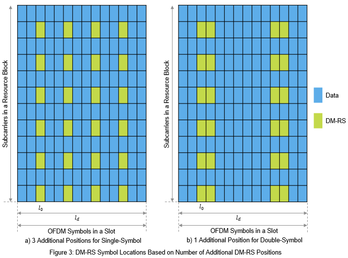
The higher-layer parameter dmrs-AdditionalPosition defines the maximum number of additional single- or double-symbol DM-RS transmitted. The number of additional positions is in the range of 0 to 3 and depends on the mapping type, DM-RS length, and PDSCH symbol allocation. The DM-RS symbol locations are given by TS 38.211 Tables 7.4.1.1.2-3, and 7.4.1.1.2-4. Figure 3 illustrates the DM-RS additional positions in combination with single-symbol and double-symbol DM-RS.
% Set the parameters that control the time resources of DM-RS
pdsch.DMRS.DMRSTypeAPosition = 2;      % 2 or 3
pdsch.DMRS.DMRSLength = 1;             % 1 or 2
pdsch.DMRS.DMRSAdditionalPosition = 1; % 0...3
Parameters That Control Frequency Domain Resources
The parameters that control the subcarrier locations of DM-RS are:
DM-RS configuration type
DM-RS antenna ports
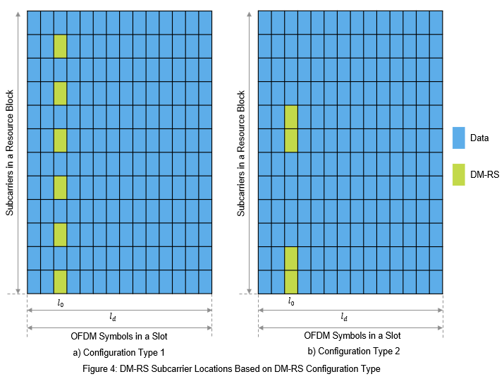
The configuration type indicates the frequency density of DM-RS and is signaled by RRC message dmrs-Type. Configuration type 1 defines six subcarriers per physical resource block (PRB) per antenna port, comprising alternate subcarriers. Configuration type 2 defines four subcarriers per PRB per antenna port, consisting of two groups of two consecutive subcarriers. Figure 4 indicates the DM-RS subcarrier locations based on configuration type.
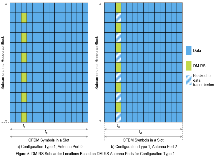
Different delta shifts are applied to the sets of subcarriers used, depending on the associated antenna port or code division multiplexing (CDM) group. For configuration type 1, there are two possible CDM groups/shifts across four antenna ports (p=0...3) for single-symbol DM-RS and eight antenna ports (p=0...7) for double-symbol DM-RS. Figure 5 illustrates how different shifts apply to DM-RS subcarrier locations when you set the configuration type to 1 for single antenna port setups. In the figure, DM-RS antenna port 0 is shown with one CDM group without data, and DM-RS antenna port 2 with two CDM groups without data.
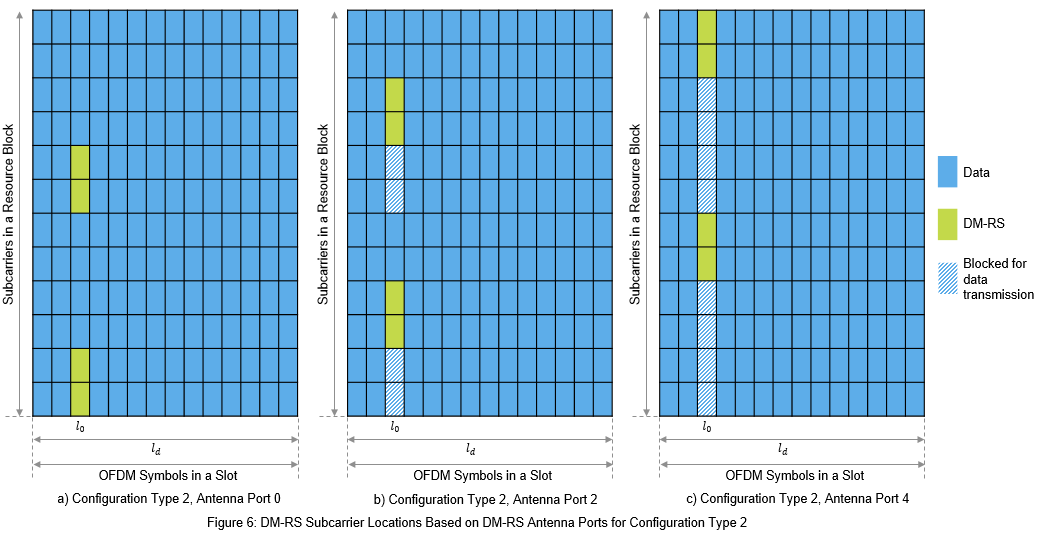
For configuration type 2, there are three possible CDM groups/shifts across six antenna ports (p=0...5) for single-symbol DM-RS and twelve antenna ports (p=0...11) for double-symbol DM-RS. Figure 6 illustrates how different shifts apply to DM-RS subcarrier locations when you set the configuration type to 2 for single antenna port setups. In the figure, DM-RS antenna port 0 is shown with one CDM group without data, DM-RS antenna port 2 with two CDM groups without data, and DM-RS antenna port 4 with three CDM groups without data. For more details on DM-RS, refer to TS 38.211 Section 7.4.1.1.
% Set the parameters that control the frequency resources of DM-RS
pdsch.DMRS.DMRSConfigurationType = 1; % 1 or 2
pdsch.DMRS.DMRSPortSet = 0;

% Set the parameter that controls the number of REs available for data
% transmission in a DM-RS carrying OFDM symbol. This value is nominally
% greater than the maximum configured CDM group number.
pdsch.DMRS.NumCDMGroupsWithoutData = 1; % 1 corresponds to CDM group number 0

% The read-only properties DeltaShifts and DMRSSubcarrierLocations of DMRS
% property of pdsch object provides the values of delta shift(s) and DM-RS
% subcarrier locations in an RB for each antenna port configured.
pdsch.DMRS.DeltaShifts
ans =
0
pdsch.DMRS.DMRSSubcarrierLocations
ans = 6×1

     0
     2
     4
     6
     8
    10
Sequence Generation
The pseudorandom sequence used for DM-RS is length gold sequence. The sequence is generated across all the common resource blocks (CRBs) and is transmitted only in the RBs allocated for data because it is not required to estimate the channel outside the frequency region in which data is not transmitted. Generating the reference signal sequence across all the CRBs ensures that the same underlying pseudorandom sequence is used for multiple UEs on overlapping time-frequency resources in the case of a multi-user MIMO. The parameters that control the sequence generation are:
DM-RS scrambling identity ()
DM-RS scrambling initialization ()
Number of OFDM symbols in a slot
Slot number in a radio frame
DM-RS symbol locations
PRBs allocation
The CyclicPrefix property of the carrier object controls the number of OFDM symbols in a slot. The NSlot property of the carrier object controls the slot number.
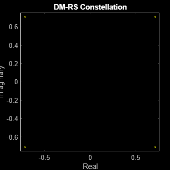
% Set the parameters that only control the DM-RS sequence generation
pdsch.DMRS.NIDNSCID = 1; % Use empty to set it to NCellID of the carrier
pdsch.DMRS.NSCID = 0;    % 0 or 1

% Generate DM-RS symbols
pdsch.NumLayers = numel(pdsch.DMRS.DMRSPortSet);
dmrsSymbols = nrPDSCHDMRS(carrier,pdsch);

% Plot the constellation
scatterplot(dmrsSymbols)
title('DM-RS Constellation')
xlabel('Real')
ylabel('Imaginary')
% The read-only properties TimeWeights and FrequencyWeights of DMRS
% property of pdsch object provides the values of time and frequency
% weights applied to the DM-RS symbols.
pdsch.DMRS.TimeWeights
ans = 2×1

     1
     1
pdsch.DMRS.FrequencyWeights
ans = 2×1

     1
     1
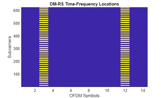
% Generate DM-RS indices
dmrsIndices = nrPDSCHDMRSIndices(carrier,pdsch);

% Map the DM-RS symbols to the grid with the help of DM-RS indices
grid = zeros([12*carrier.NSizeGrid carrier.SymbolsPerSlot pdsch.NumLayers]);
grid(dmrsIndices) = dmrsSymbols;
figure
imagesc(abs(grid(:,:,1)));
axis xy;
xlabel('OFDM Symbols');
ylabel('Subcarriers');
title('DM-RS Time-Frequency Locations');
PT-RS
PT-RS is the phase tracking reference signal. PT-RS is used mainly to estimate and minimize the effect of CPE on system performance. Due to the phase noise properties, PT-RS signal has a low density in the frequency domain and a high density in the time domain. PT-RS always occurs in combination with DM-RS and only when the network has configured PT-RS to be present.
Parameters That Control Time Domain Resources
PT-RS is configured through the higher layer parameter DMRS-DownlinkConfig for downlink. The parameters that control the time resources of PT-RS are:
DM-RS symbol locations
Time density of PT-RS ()
depends on the scheduled modulation and coding scheme. Value of must be from the set {1, 2, 4}. For the parameters that control DM-RS symbol locations, refer to Parameters that Control DM-RS Time Resources.
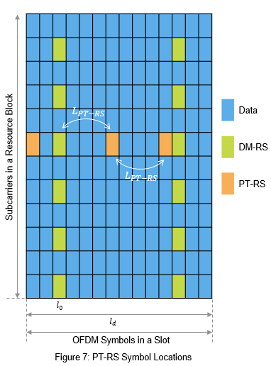
The PT-RS symbol locations in a slot start from the first OFDM symbol in the shared channel allocation and hop every symbols, if no DM-RS symbol is present in this interval. In the case where a DM-RS symbol or symbols are present in between or at the hop interval, the hop starts from the last DM-RS symbol location to provide the next PT-RS symbol. Figure 7 shows the PT-RS symbol locations in an RB for single slot with time-density set to 4 and DM-RS symbol locations set to 2 and 11 (0-based).
% Set the EnablePTRS property in pdsch to 1
pdsch.EnablePTRS = 1;

% Set the parameters that control the time resources of PT-RS
pdsch.PTRS.TimeDensity = 4;
Parameters That Control Frequency Domain Resources
PT-RS occupies only one subcarrier in an RB for one OFDM symbol. The parameters that control the frequency resources of PT-RS are:
PRB allocation
DM-RS configuration type
Frequency density of PT-RS ()
Radio network temporary identifier ()
Resource element offset
PT-RS antenna port
depends on the scheduled bandwidth. The value of is either 2 or 4, which indicates whether PT-RS is present in every two RBs or every four RBs.
The starting RB at which PT-RS is present (), depends on , , and the number of RBs () allocated for PDSCH. For the purpose of mapping PT-RS, all the RBs of PDSCH are numbered in increasing order from 0 to . The subcarrier location of PT-RS () within a resource block depends on the DM-RS configuration type, resource element (RE) offset, and PT-RS antenna port. The PT-RS antenna port must be a subset of DM-RS antenna ports. The PT-RS subcarrier location always aligns with one of the DM-RS subcarrier locations in an RB.
PT-RS in an RB occupies the same subcarrier locations in all the OFDM symbols where PT-RS is present.
% Set the parameters that affect the PT-RS subcarrier locations
pdsch.RNTI = 1;
pdsch.PTRS.FrequencyDensity = 2; % 2 or 4
pdsch.PTRS.REOffset = '10';      % '00', '01', '10', '11'
pdsch.PTRS.PTRSPortSet = min(pdsch.DMRS.DMRSPortSet);

% Set the other parameters that control PT-RS subcarrier locations
pdsch.DMRS.DMRSConfigurationType = 1;
pdsch.DMRS.DMRSPortSet = 0;
Sequence Generation
The sequence used to generate PT-RS is the same pseudorandom sequence used for DM-RS sequence generation. The values of the PT-RS sequence depend on the position of the first DM-RS symbol. For more details, refer to DM-RS sequence generation.
% Set the parameters that control the PT-RS sequence generation
pdsch.DMRS.NIDNSCID = 1; % Use empty to set it to NCellID of the carrier
pdsch.DMRS.NSCID = 0;    % 0 or 1

% Generate PT-RS symbols
carrier.NSizeGrid = 4;
pdsch.PRBSet = 0:carrier.NSizeGrid-1;
pdsch.NumLayers = numel(pdsch.DMRS.DMRSPortSet);
ptrsSymbols = nrPDSCHPTRS(carrier,pdsch);

% Generate PT-RS indices
ptrsIndices = nrPDSCHPTRSIndices(carrier,pdsch);
Get DM-RS symbols, RE indices of PDSCH, and DM-RS.
% PDSCH indices, DM-RS symbols and indices
[pdschIndices, pdschInfo] = nrPDSCHIndices(carrier,pdsch);
dmrsIndices = nrPDSCHDMRSIndices(carrier,pdsch);
dmrsSymbols = nrPDSCHDMRS(carrier,pdsch);
Map PDSCH, DM-RS, and PT-RS RE indices to the grid with scaled values to visualize the respective locations on the grid.
chpLevel = struct;
chpLevel.PDSCH = 0.4;
chpLevel.DMRS = 1;
chpLevel.PTRS = 1.4;
nSlotSymb = carrier.SymbolsPerSlot;
grid = complex(zeros(carrier.NSizeGrid*12,nSlotSymb,pdsch.NumLayers));
grid(pdschIndices) = chpLevel.PDSCH;
grid(dmrsIndices) = chpLevel.DMRS*dmrsSymbols;
grid(ptrsIndices) = chpLevel.PTRS*ptrsSymbols;
map = parula(64);
cscaling = 40;
im = image(cscaling*abs(grid(:,:,1)));
colormap(im.Parent,map);

% Add legend to the image
chpval = struct2cell(chpLevel);
clevels = cscaling*[chpval{:}];
N = length(clevels);
L = line(ones(N),ones(N), 'LineWidth',8); % Generate lines
% Index the color map and associated the selected colors with the lines
set(L,{'color'},mat2cell(map( min(1+clevels,length(map) ),:),ones(1,N),3)); % Set the colors according to map
% Create legend
fnames = {'PDSCH','DM-RS','PT-RS'};
legend(fnames{:});
axis xy
title('Carrier Grid Containing PDSCH, DM-RS and PT-RS')
xlabel('OFDM Symbols')
ylabel('Subcarriers')
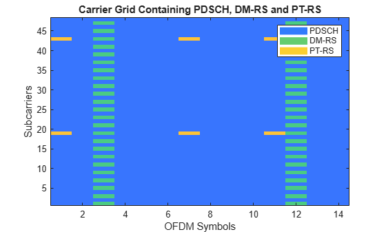
In the preceding figure, PT-RS is located at the start of the OFDM symbol in the PDSCH allocation. The symbols are present at every hop interval from each other or from DM-RS symbols. PT-RS symbols in the frequency domain are located at subcarrier 19 (first RB) and at subcarrier 43 (third RB) of each OFDM symbol where PT-RS is present. The difference in consecutive subcarrier locations of PT-RS is 24, which is the number of subcarriers in an RB (12) times the frequency density of PT-RS (2).
Further Exploration
You can try changing the parameters that affect the time and frequency resources of reference signals and observe the variations in the RE positions for the respective signals.
Try performing channel estimation and phase tracking by using the reference signals. Compute the throughput by following the steps outlined in NR PDSCH Throughput.
This example shows how to generate the DM-RS and PT-RS sequences, and how to map the sequences to the OFDM carrier resource grid. It highlights the properties that control the time-frequency structure of reference signals.
References
3GPP TS 38.211. "NR; Physical channels and modulation" 3rd Generation Partnership Project; Technical Specification Group Radio Access Network.
3GPP TS 38.214. "NR; Physical layer procedures for data" 3rd Generation Partnership Project; Technical Specification Group Radio Access Network.
3GPP TS 38.212. "NR; Multiplexing and channel coding" 3rd Generation Partnership Project; Technical Specification Group Radio Access Network.