Main Content

wlanDMGDataBitRecover

Recover bits from DMG Data field

Description

example

dataBits = wlanDMGDataBitRecover(rxData,noiseVarEst,cfgDMG) recovers dataBits, a column vector of bits, from rxData, the DMG Data field of a directional multi-gigabit (DMG) transmission. The function recovers dataBits by using noise variance estimate noiseVarEst and DMG transmission parameters cfgDMG.

example

dataBits = wlanDMGDataBitRecover(rxData,noiseVarEst,csi,cfgDMG) enhances the demapping of OFDM subcarriers by using channel state information csi. Use this syntax for DMG transmissions that use an orthogonal frequency-division multiplexing (OFDM) PHY configuration.

example

dataBits = wlanDMGDataBitRecover(___,Name,Value) specifies algorithm options by using one or more name-value pair arguments, in addition to any input argument combination from previous syntaxes. For example, 'LDPCDecodingMethod','layered-bp' specifies the layered belief propagation low-density parity-check (LDPC) decoding algorithm.

Examples

collapse all

Recover bits from the DMG Data field in a control transmission.

Create a DMG configuration object with a modulation and coding scheme (MCS) for a control PHY configuration.

cfgDMG = wlanDMGConfig('MCS',0);

Create a sequence of data bits and generate a DMG waveform.

bits = randi([0 1],cfgDMG.PSDULength*8,1,'int8'); 
waveform = wlanWaveformGenerator(bits,cfgDMG);

Pass the waveform through a noiseless channel.

noiseVarEst = 0;

Extract the DMG Header and the DMG Data fields by using the wlanFieldIndices function.

ind = wlanFieldIndices(cfgDMG);
rxSym = waveform(ind.DMGHeader(1):ind.DMGData(2));

Rotate the received signal by 90 degrees.

rxSymRotated = rxSym.*exp(-1i*(pi/2)*(0:size(rxSym,1) - 1).');

Generate a Golay sequence of length 32 by using the wlanGolaySequence function.

len = 32;
Ga = wlanGolaySequence(len);

Despread the signal with a factor equal to the Golay sequence length

rxData = (reshape(rxSymRotated,len,length(rxSymRotated)/len)'*Ga)/len;

Recover the PSDU from the DMG Data field.

dataBits = wlanDMGDataBitRecover(rxData,noiseVarEst,cfgDMG);

Confirm that the decoded bits match the transmitted bits.

disp(isequal(bits,dataBits))
   1

Recover bits from the DMG Data field of an OFDM transmission.

Configure an OFDM transmission by creating a DMG configuration object with an MCS of 14.

cfgDMG = wlanDMGConfig('MCS',14);

Create a sequence of data bits and generate a DMG waveform.

bits = randi([0 1],8*cfgDMG.PSDULength,1,'int8'); 
waveform = wlanWaveformGenerator(bits,cfgDMG);

Pass the waveform through a channel, assuming additive white Gaussian noise (AWGN) for the specified signal-to-noise ratio (SNR).

snr = 10;                      % SNR, in dB
noiseVarEst = 10^(-snr/10);    % Noise variance
rxSig = awgn(waveform,snr);

Extract the DMG Data field from the received signal.

ind = wlanFieldIndices(cfgDMG);
rxSym = rxSig(ind.DMGData(1):ind.DMGData(2));

Perform OFDM demodulation on the received waveform and extract the data subcarriers.

demod = wlanDMGOFDMDemodulate(rxSym);
info = wlanDMGOFDMInfo;
rxData = demod(info.DataIndices,:);

Recover the PSDU from the DMG Data field, assuming a CSI estimate of all ones.

csi = ones(length(info.DataIndices),1);
dataBits = wlanDMGDataBitRecover(rxData,noiseVarEst,csi,cfgDMG);

Confirm that the decoded bits match the transmitted bits.

disp(isequal(bits,dataBits))
   1

Recover bits from the DMG Data field of a single-carrier (SC) transmission.

Configure an SC transmission by creating a DMG configuration object with an MCS of 10.

cfgDMG = wlanDMGConfig('MCS',10);

Create a sequence of data bits and generate a DMG waveform.

bits = randi([0 1],8*cfgDMG.PSDULength,1,'int8'); 
waveform = wlanWaveformGenerator(bits,cfgDMG);

Pass the waveform through a channel, assuming AWGN with an SNR of 10 dB.

snr = 10;                       % SNR, in dB
noiseVarEst = 10^(-snr/10);     % Noise variance
rxSig = awgn(waveform,snr);

Extract the DMG Data field from the received signal.

ind = wlanFieldIndices(cfgDMG);
rxSym = rxSig(ind.DMGData(1):ind.DMGData(2));

Reshape the received data waveform into blocks. Set the data block size to 512 and the guard interval (GI) length to 64. Remove the last GI from the received waveform. The resulting waveform is a 512-by-Nblks matrix, where Nblks is the number of DMG data blocks.

blkSize = 512;                                    % Block size
Ngi = 64;                                         % GI length
rxSymNoGI = rxSym(1:end-Ngi);                     % Remove GI
rxSymReshaped = reshape(rxSymNoGI,blkSize,[]);    % Reshape received data

Remove the GI from each block. Confirm that the resulting signal is a 448-by-Nblks matrix, as expected for the time-domain DMG Data field signal in an SC PHY configuration.

rxData = rxSymReshaped(Ngi+1:end,:);
disp(size(rxData))
   448     9

Recover the PSDU from the DMG Data field, specifying layered belief propagation LDPC decoding.

dataBits = wlanDMGDataBitRecover(rxData,noiseVarEst,cfgDMG,'LDPCDecodingMethod','norm-min-sum');

Confirm that the decoded bits match the original information bits.

disp(isequal(bits,dataBits))
   1

Input Arguments

collapse all

Received DMG Data field, specified as a column vector or matrix. The contents and size of this input depend on the PHY configuration you specify in the cfgDMG input.

  • SC PHY — This input contains the time-domain DMG Data field signal in a 448-by-Nblks matrix. The value 448 is the number of symbols in a DMG Data block, and Nblks is the number of DMG Data blocks. For more information about block transmission, see section 21.6.3.2.5 of [1]

  • OFDM PHY — This input contains the demodulated DMG Data field OFDM symbols in a 336-by-Nsym matrix. The value 336 is the number of data subcarriers in the DMG Data field and Nsym is the number of OFDM symbols.

  • Control PHY — This input contains the time-domain DMG Header and DMG Data fields in a column vector of length Nb, where Nb is the number of despread symbols.

Data Types: double
Complex Number Support: Yes

Noise variance estimate, specified as a nonnegative scalar.

Data Types: double

DMG transmission configuration, specified as a wlanDMGConfig object.

Channel state information, specified as a real-valued column vector of length 336. The value 336 specifies the number of data subcarriers in the DMG Data field.

Dependencies

To enable this input, specify an OFDM PHY configuration in the cfgDMG input.

Data Types: double

Name-Value Arguments

Specify optional pairs of arguments as Name1=Value1,...,NameN=ValueN, where Name is the argument name and Value is the corresponding value. Name-value arguments must appear after other arguments, but the order of the pairs does not matter.

Before R2021a, use commas to separate each name and value, and enclose Name in quotes.

Example: 'MaximumLDPCIterationCount','12','EarlyTermination','false' specifies a maximum of 12 LDPC decoding iterations and disables early termination so that the decoder completes the 12 iterations.

LDPC decoding algorithm, specified as the comma-separated pair consisting of 'LDPCDecodingMethod' and one of these values.

  • 'bp' — Use the belief propagation (BP) decoding algorithm. For more information, see Belief Propagation Decoding.

  • 'layered-bp' — Use the layered BP decoding algorithm, suitable for quasi-cyclic parity check matrices (PCMs). For more information, see Layered Belief Propagation Decoding.

  • 'norm-min-sum' — Use the layered BP decoding algorithm with the normalized min-sum approximation. For more information, see Normalized Min-Sum Decoding.

  • 'offset-min-sum' — Use the layered BP decoding algorithm with the offset min-sum approximation. For more information, see Offset Min-Sum Decoding.

Data Types: char | string

Scaling factor for normalized min-sum LDPC decoding, specified as the name-value argument consisting of MinSumScalingFactor and a scalar in the interval (0, 1].

Dependencies

To enable this argument, specify the 'LDPCDecodingMethod' name-value argument as "norm-min-sum".

Data Types: double

Offset for offset min-sum LDPC decoding, specified as the name-value argument consisting of MinSumOffset and a nonnegative scalar.

Dependencies

To enable this argument, specify the 'LDPCDecodingMethod' name-value argument as offset-min-sum.

Data Types: double

Maximum number of LDPC decoding iterations, specified as the comma-separated pair consisting of 'MaximumLDPCIterationCount' and a positive integer.

Data Types: double

Enable early termination of LDPC decoding, specified as the comma-separated pair consisting of 'EarlyTermination' and 1 (true) or 0 (false).

  • When you set this value to 0 (false), LDPC decoding completes the number of iterations specified in the 'MaximumLDPCIterationCount' name-value pair argument regardless of parity check status.

  • When you set this value to 1 (true), LDPC decoding terminates when all parity checks are satisfied.

Data Types: logical

Output Arguments

collapse all

Bits recovered from the DMG Data field, returned as 1, 0, or a binary-valued column vector of length 8 × L, where L is the PSDU length in bytes.

Data Types: int8

More About

collapse all

DMG Data Field

The DMG format supports three PHY modulation schemes: control, single-carrier (SC), and OFDM. The DMG Data field serves the same function for all three PHY types and carries the user data payload. The length of the DMG Data field differs between PHY types.

Data field of DMG format PPDU. See the packet structure of single carrier PHY and OFDM PHY

Data field of DMG format PPDU. See the packet structure of single carrier PHY and OFDM PHY

For SC PHY, each block in the data field is 512 symbols long and has a guard interval (GI) of 64 symbols with the Golay Sequence. For OFDM, each OFDM symbol in the data field is 640 samples long and has a cyclic prefix (CP) of 128 samples to prevent intersymbol interference.

IEEE 802.11ad™-2012 specifies the common aspects of the DMG PPDU packet structure in Section 21.3. The PHY modulation-specific aspects of the data field structure are specified in these sections.

  • The DMG control PHY packet structure is specified in Section 21.4.

  • The DMG OFDM PHY packet structure is specified in Section 21.5.

  • The DMG SC PHY packet structure is specified in Section 21.6.

Algorithms

collapse all

This function supports these four LDPC decoding algorithms.

Belief Propagation Decoding

The function implements the BP algorithm based on the decoding algorithm presented in [2]. For transmitted LDPC-encoded codeword c=(c0,c1,,cn1), the input to the LDPC decoder is the log-likelihood ratio (LLR) given by

L(ci)=log(Pr(ci=0|channel output for ci)Pr(ci=0|channel output for ci)).

In each iteration, the function updates the key components of the algorithm based on these equations:

L(rji)=2atanh(iVj\{i}tanh(12L(qij))),

L(qij)=L(ci)+j'Ci\{j}L(rji), initialized as L(qij)=L(ci) before the first iteration, and

L(Qi)=L(ci)+jCiL(rji).

At the end of each iteration, L(Qi) is an updated estimate of the LLR value for the transmitted bit, ci. The value L(Qi) is the soft-decision output for ci. If L(Qi) is negative, the hard-decision output for ci is 1. Otherwise, the output is 0.

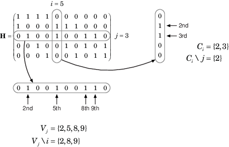
Index sets Ci\{j} and Vj\{i} are based on the PCM such that the sets Ci and Vj correspond to all nonzero elements in column i and row j of the PCM, respectively.

This figure demonstrates how to compute these index sets for PCM H for the case i = 5 and j = 3.

Compute index sets for PCM

To avoid infinite numbers in the algorithm equations, atanh(1) and atanh(–1) are set to 19.07 and –19.07, respectively. Due to finite precision, MATLAB® returns 1 for tanh(19.07) and –1 for tanh(–19.07).

When you specify the 'EarlyTermination' name-value pair argument as 0 (false), the decoding terminates after the number of iterations specified by the 'MaximumLDPCIterationCount' name-value pair argument. When you specify the 'EarlyTermination' name-value pair argument as 1 (true), the decoding terminates when all parity checks are satisfied (HcT=0) or after the number of iterations specified by the 'MaximumLDPCIterationCount' name-value pair argument.

Layered Belief Propagation Decoding

The function implements the layered BP algorithm based on the decoding algorithm presented in Section II.A of [3]. The decoding loop iterates over subsets of rows (layers) of the PCM. For each row, m, in a layer and each bit index, j, the implementation updates the key components of the algorithm based on these equations.

(1) L(qmj)=L(qj)Rmj

(2) Ψ(x)=log(|tanh(x/2)|)

(3) Amj=nN(m)\{j}Ψ(L(qmn))

(4) smj=nN(m)\{j}sgn(L(qmn))

(5) Rmj=smjΨ(Amj)

(6) L(qj)=L(qmj)+Rmj

For each layer, the decoding equation (6) works on the combined input obtained from the current LLR inputs, L(qmj), and the previous layer updates, Rmj.

Because the layered BP algorithm updates only a subset of the nodes in a layer, this algorithm is faster than the BP algorithm. To achieve the same error rate as attained with BP decoding, use half the number of decoding iterations when using the layered BP algorithm.

Normalized Min-Sum Decoding

The function implements the normalized min-sum decoding algorithm by following the layered BP algorithm with equation (3) replaced by

Amj=minnN(m)\{j}(α|L(qmn)|),

where α is the scaling factor specified by the 'MinSumScalingFactor' name-value pair argument. This equation is an adaptation of equation (4) presented in [4].

Offset Min-Sum Decoding

The function implements the offset min-sum decoding algorithm by following the layered BP algorithm with equation (3) replaced by

Amj=max(minnN(m)\{j}(|L(qmn)|β), 0),

where β is the offset specified by the 'MinSumOffset' name-value pair argument. This equation is an adaptation of equation (5) presented in [4].

References

[1] IEEE STD 802.11ad-2012 (Amendment to IEEE Std 802.11™-2012, as amended by IEEE Std 802.11ae™-2012 and IEEE Std 802.11a™-2012). “Part 11: Wireless LAN Medium Access Control (MAC) and Physical Layer (PHY) Specifications. Amendment 4: Enhancements for Very High Throughput Operation in Bands below 6 GHz.” IEEE Standard for Information technology — Telecommunications and information exchange between systems. Local and metropolitan area networks — Specific requirements.

[2] Gallager, Robert G. Low-Density Parity-Check Codes. Cambridge, MA: MIT Press, 1963.

[3] Hocevar, D.E. "A Reduced Complexity Decoder Architecture via Layered Decoding of LDPC Codes." In IEEE Workshop on Signal Processing Systems, 2004. SIPS 2004., 107-12. Austin, Texas, USA: IEEE, 2004. https://doi.org/10.1109/SIPS.2004.1363033.

[4] Jinghu Chen, R.M. Tanner, C. Jones, and Yan Li. "Improved Min-Sum Decoding Algorithms for Irregular LDPC Codes." In Proceedings. International Symposium on Information Theory, 2005. ISIT 2005., 449-53, 2005. https://doi.org/10.1109/ISIT.2005.1523374.

Extended Capabilities

C/C++ Code Generation
Generate C and C++ code using MATLAB® Coder™.

Version History

Introduced in R2017b