Modulate Data Bits Using GMSK
This example shows how to use the GMSK Modulator block in Wireless HDL Toolbox™ to modulate data bits to symbols using Gaussian minimum shift keying (GMSK) method. In this example, to verify the behavior of the block, compare the output of the block with the output of the comm.GMSKModulator object in Communications Toolbox™. The example shows the eye diagram for the block for the specified pulse length. The Simulink® model in this example supports HDL code generation for the GMSKMod subsystem.
Set Up Input Parameters
Set up these workspace variables for the Simulink model to use. The model in this example uses these workspace variables BT, L, sps, inPhaseOffset, LUTSize, outWL, and symPreHist to configure the GMSK Modulator block. You can modify these values according to your requirement.
BT = 0.41;         % Bandwidth time product
L = 6;             % Pulse length
sps = 4;           % Number of samples per symbol
inPhaseOffset = 0; % Initial phase offset value
LUTSize = 2^16;    % Number of data points
outWL = 16;        % Output word length
bitInput = 'on';
symPreHist = [1 1 -1 1 1];
snr = 30;
rng('default');
dataLength = 100;
Generate Input Data
Generate random data bits and a valid signal to provide as an input to the GMSK Modulator block and the comm.GMSKModulator object.
if strcmp(bitInput,'on')
    dataIn = logical(randn(dataLength,1)>0); %#ok<*UNRCH>
    bitInpForComms = true;
else
    dataIn = 2*logical(randn(dataLength,1)>0)-1;
    bitInpForComms = false;
end
validIn = true(dataLength,1);
stopTime = dataLength+24;
Run Model
The GMSKMod subsystem contains the GMSK Modulator block. Running the model imports the input signal variables BT, L, sps, inPhaseOffset, LUTSize, outWL, and symPreHist and exports dataOut and a control signal validOut to the MATLAB® workspace.
load_system("gmskMod.slx");
sim("gmskMod.slx");
simulinkOut = dataOut(validOut,:).';
simulinkOut = simulinkOut(:);
Generate Reference Data
Provide input data bits to the comm.GMSKModulator object. Use the output of this object as a reference to verify the output of the block.
gmskMod = comm.GMSKModulator('BitInput', bitInpForComms,...
    'InitialPhaseOffset', inPhaseOffset,...
    'BandwidthTimeProduct',BT, ...
    'SamplesPerSymbol',sps,...
    'PulseLength',L,...
    'SymbolPrehistory',symPreHist);
matlabOut = gmskMod(dataIn);

channel = comm.AWGNChannel('NoiseMethod', ...
                           'Signal to noise ratio (SNR)', ...
                           'SNR',snr);
noisySignalMAT = channel(matlabOut);
release(channel);
noisySignalSim = channel(double(simulinkOut));
Compare Block Output with Reference Object Output
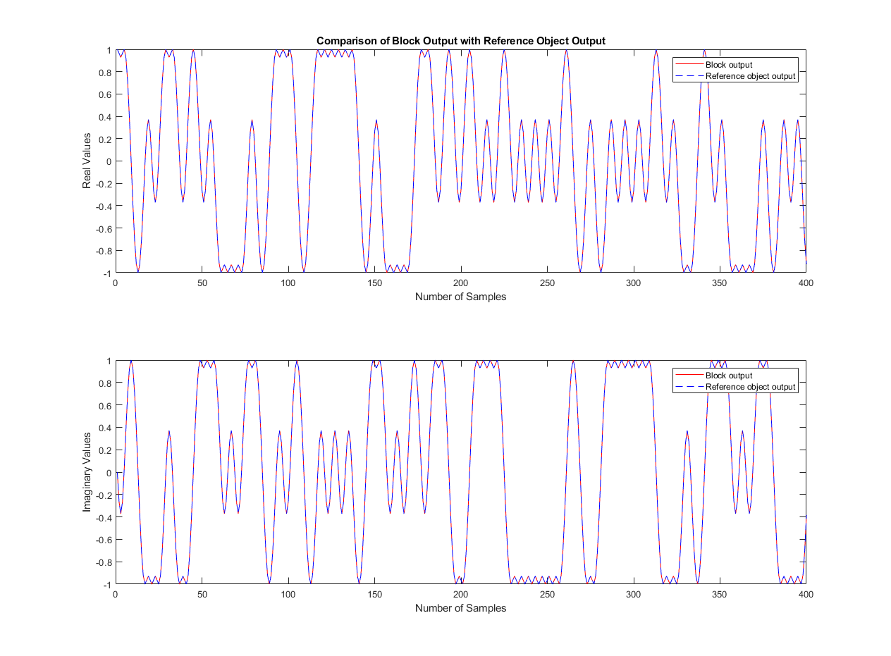
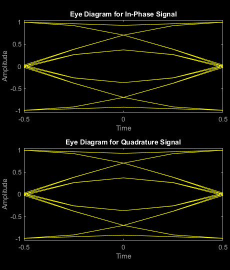
Compare the Simulink block output with the output of the MATLAB object. You can see the comparison results on the graph. Also, the eyediagram scope displays the in-phase and quadrature of the output signal.
figure('units','normalized','outerposition',[0 0 1 1])
subplot(2,1,1)

plot(real(matlabOut),'r');
hold on;
plot(real(simulinkOut),'--b');
legend('Block output','Reference object output')
xlabel('Number of Samples');
ylabel('Real Values');
title('Comparison of Block Output with Reference Object Output')
subplot(2,1,2)

plot(imag(matlabOut),'r');
hold on;
plot(imag(simulinkOut),'--b');
legend('Block output','Reference object output')
xlabel('Number of Samples');
ylabel('Imaginary Values');

eyediagram(noisySignalSim,sps,1,sps/2)

