Implement CAN Network for Robotic Arm in Simulink
This example shows you how to use Vehicle Network Toolbox™ and Simulink® to implement a Controller Area Network (CAN) in a remote manipulator arm.
Vehicle Network Toolbox provides Simulink blocks for transmitting and receiving live messages via Simulink models over Controller Area Networks (CAN). This example uses the CAN Configuration, CAN Pack, CAN Transmit, CAN Receive, and CAN Unpack blocks to perform data transfer over a CAN bus. The CAN messages used are defined in the CAN database file, canDatabaseFor6DofRoboticArm.dbc.
This example uses MathWorks® virtual CAN channels. Alternatively, you can connect your models to other supported hardware.
Model Description


The model consists of the following subsystems: Manipulator arm system, Inverse kinematics and controller, Joint CAN transmit interface, Joint CAN receive interface, Inverse kinematics and controller CAN transmit interface, and Inverse kinematics and controller CAN receive interface. Each joint and the inverse kinematics and controller subsystem constitute a node in the CAN bus.
The user inputs the position coordinates (X, Y and Z in metres) and the orientation (roll, pitch and yaw angles in degrees, in body-3 2-3-1 sequence) of the end effector. The inverse kinematics and controller subsystem receives feedback from the joint angle sensors that are sent via the CAN bus, and sends appropriate commands to each joint motor via the CAN bus to drive the position anf the orientation of the end effector to the user-input values.
The remote manipulator arm is assumed to be attached to a spacecraft in orbit. As a result, gravity is neglected.
Manipulator Arm System
This subsystem consists of the rigid-body model of the remote manipulator arm, modeled using Simscape™ Multibody™ 2G. The arm has six joints. Each joint is actuated by a DC motor with a gearbox, and are modeled using Simscape Foundational Library. Each joint also has a joint angle sensor. The sensor data in sent into the CAN bus. Each motor is powered by a controlled voltage source. The voltage sources receive messages from the CAN bus and apply the DC voltage across their terminals corresponding to the information in the messages.
Inverse Kinematics and Controller
The Inverse kinematics and controller subsystem further implements the inverse kinematics and the control algorithm. The inverse kinematics computes the desired joint angles from the desired position (X, Y and Z) and orientation (roll, pitch and yaw angles) that are input by the user. The discrete PID controllers utilize the joint angle sensor values that are read from the CAN bus to determine the DC voltage that should be applied to each motor to drive the joint angles to the desired values. The DC voltage values are sent as messages in the CAN bus.
Joint CAN Transmit Interface
This subsystem consists of the VNT blocks that are necessary to transmit the joint angle values from the corresponding sensors into the CAN bus.
Joint CAN Receive Interface
This subsystem consists of the VNT blocks that are necessary to receive and unpack the messages from the CAN bus that contain information about the DC voltages that need to be applied to the controlled voltage sources corresponding to each motor.
Inverse Kinematics and Controller CAN Transmit Interface
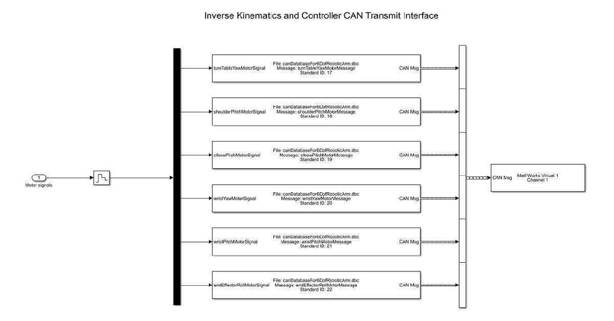
This subsystem consists of the VNT blocks that are necessary to transmit the motor signals (DC voltages that need to be applied across the controlled voltage sources) calculated by the Inverse Kinematics and Controller subsystem into the CAN bus.
Inverse Kinematics and Controller CAN Receive Interface
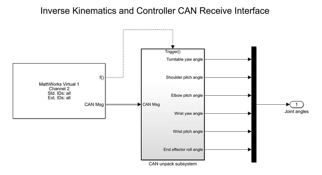
This subsystem consists of the VNT blocks that are necessary to receive the messages from the CAN bus that contain information about the joint angles that are sent by the joint angle sensors.