Stereo Image Rectification and Disparity Using Semi-Global Block Matching
This example shows how to implement stereo image rectification for a calibrated stereo camera pair and then compute disparity between the pair using the Semi-Global Block Matching algorithm. The SGBM method is an intensity-based approach and generates a dense and smooth disparity map for good 3D reconstruction. However, it is highly compute-intensive and requires hardware acceleration using FPGA to obtain real-time performance. The example modules have similar behavior in function to the Computer Vision Toolbox™ rectifyStereoImages and disparitySGM functions. This example is based on the Vision HDL Toolbox™ examples, Stereo Image Rectification and Stereo Disparity Using Semi-Global Block Matching.
Stereo image rectification projects images onto a common image plane in such a way that the corresponding points in the two stereo images have the same row coordinates. This image projection corrects the images to appear as if the two cameras are parallel. With a rectified stereo camera, depth can be inferred from point correspondences using triangulation. Depth at any given point can be computed if the disparity at that point is known. Disparity measures the displacement of a point between two images. The higher the disparity, the closer the object.
The example model presented here is FPGA-hardware compatible, and can therefore provide real-time performance.
Model Overview
In the example model, the LeftInputImage and RightInputImage blocks import the stereo left and right images from files. The Frame To Pixels blocks convert these stereo image frames to pixel streams with pixelcontrol buses for input to the StereoImageProcessingHDL subsystem. After stereo image rectification, this block estimates approximate disparity of a pixel in the left image from the same pixel in the right image. The Pixels To Frame blocks convert the streams of output pixels back to frames, to be viewed by the VideoViewer.

Model Configuration
The StereoImageProcessingHDL subsystem supports the following configuration parameters:
Number of Disparity Levels: Disparity levels is a parameter used to define the search space for matching. For a given image resolution, increasing the disparity level reduces the minimum distance to detect depth. Increasing the disparity level also increases the hardware resources used for the algorithm. At a given disparity level, increasing the image resolution increases the minimum distance to detect depth. Increasing the image resolution also increases the accuracy of depth estimation. The number of disparity levels are proportional to the input image resolution for detection of objects at the same depth. This example supports disparity levels from 8 to 128 (both values inclusive).
Uniqueness Threshold: The uniqueness function ensures reliability of the computed minimum disparity. A higher value of the uniqueness threshold marks more disparities unreliable. The uniqueness threshold must be a positive integer value, between 0 and 100 with a typical range from 5 to 15. The default value of uniqueness threshold is 5.
HDL Implementation
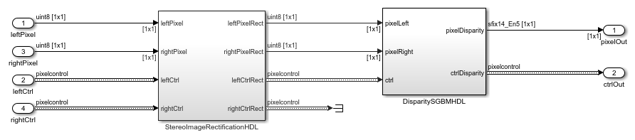
The StereoImageProcessingHDL subsystem consists of the StereoImageRectificationHDL and DisparitySGBMHDL subsystems. The StereoImageRectificationHDL performs stereo image rectification using a reverse mapping technique to map the pixel locations of the output rectified image to the pixels in the input camera image. The rectified output pixel values are then processed by the DisparitySGBMHDL subsystem. Using the Semi-Global block matching approach, the DisparitySGBMHDL subsystem uses information from neighboring pixels in multiple directions to calculate the disparity of a pixel.
Stereo Image Rectification
This subsystem performs the inverse geometric transform, undistortion, and interpolation to generate the rectified output pixel values. The RectifiedCoordinateGeneration subsystem generates the row and column pixel coordinates of the output rectified and undistorted image, which are then mapped to the corresponding coordinates of the distorted image and then to the input camera image using the InverseGeometricTransform and Undistortion subsystems. For more information, see Stereo Image Rectification.

Stereo Disparity Using Semi-Global Block Matching
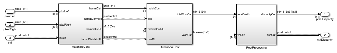
The DisparitySGBMHDL subsystem performs disparity estimation using three computation modules, matching cost calculation, directional cost calculation, and post-processing. The MatchingCost module computes the CSCT on each of the left and right images using a sliding window. For a given pixel, a 9-by-7 pixel window is considered around it. The center pixel in each window is estimated by comparing the value of each pixel with its center-symmetric counterpart in the window. If the pixel value is larger than its counterpart, the result is 1, otherwise the result is 0. This example analyzes these five directions: left-to-right, top-left-to-bottom-right, top-to-bottom, top-right-to-bottom-left, and right-to-left, and uses a DirectionalCost subsystem to accumulate disparity cost in each direction. The PostProcessing module finds the index corresponding to the minimum cost for a given pixel. For more information, see Stereo Disparity Using Semi-Global Block Matching.
Simulation Results
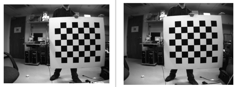
This example uses 960-by-1280 stereo images. The input pixels use the uint8 data type. The figure shows sample input images and the calculated disparity map. The model parameters for the output shown use 64 disparity levels, a uniqueness threshold of 5 and Census Transform window size of '9 x 7'. Since the first 64 columns are unused in the disparity computation, the unused pixels are padded with zeroes to generate output image of size 960-by-1280 as shown in VideoViewer. Higher disparity values in the result indicate that the object is nearer to the camera and lower disparity values indicate farther objects.

Hardware Optimization and Synthesis Results
To save hardware resources, the following hardware implementation configuration settings are updated:
Setting the DSPStyle to 'on': DSPStyle enables you to generate code that includes synthesis attributes for multiplier mapping to DSPs in your hardware design. This saves CLB LUTs to be used for other logic in the design.
Mapping delay blocks to use RAM: The 'UseRAM' implementation parameter enables using RAM-based mapping for a Delay block instead of mapping to a shift register. Mapping of the delay blocks to RAM saves CLB Registers.
Defining RAM blocks 'RAMdirective': Using 'RAMDirective', you can specify whether you want to map the Random Access Memory (RAM) blocks in your Simulink model to FPGA RAM memory blocks. You can map large memory blocks such as 'ultra' from the AMD® family. This allows us to save block RAM Tiles and map the additional memory to URAM.
Streaming factor for ForEach Subsystems: The streaming factor specifies the number of parallel data paths, or vectors, to transform into serial, scalar data paths by time-multiplexing serial data paths and sharing hardware resources. Increasing this factor saves resources in ForEach Subsystems.
You can generate HDL code for the StereoImageProcessingHDL subsystem. You must have an HDL Coder™ license to generate HDL code. This design was synthesized for the AMD® Zynq® UltraScale+(TM) MPSoC ZCU102 FPGA and the default settings are chosen. The HDL design achieves a synthesis frequency of around 70 MHz. The table shows the resource utilization for the subsystem.
% ===================================================================
% |Model Name             ||        StereoImageProcessingHDL        ||
% ===================================================================
% |Input Image Resolution ||            960 x 1280                  ||
% |CLB LUTs               ||          177710 (64.84%)               ||
% |CLB Registers          ||           77344 (14.11%)               ||
% |DSPs                   ||             209 (8.29%)                ||
% |Block RAM Tiles        ||             208 (22.81%)               ||
% ===================================================================
References
[1] G. Bradski and A. Kaehler, Learning OpenCV : Computer Vision with the OpenCV Library. Sebastopol, CA: O'Reilly, 2008.
[2] Hirschmuller H., Accurate and Efficient Stereo Processing by Semi-Global Matching and Mutual Information, International Conference on Computer Vision and Pattern Recognition, 2005.
[3] Spangenberg R., Langner T., and Rojas R., Weighted Semi-Global matching and Center-Symmetric Census Transform for Robust Driver Assistance, Computer Analysis of Images and Patterns, 2013.
[4] Gehrig S., Eberli F., and Meyer T., A Real-Time Low-Power Stereo Vision Engine Using Semi-Global Matching, International Conference on Computer Vision System, 2009.